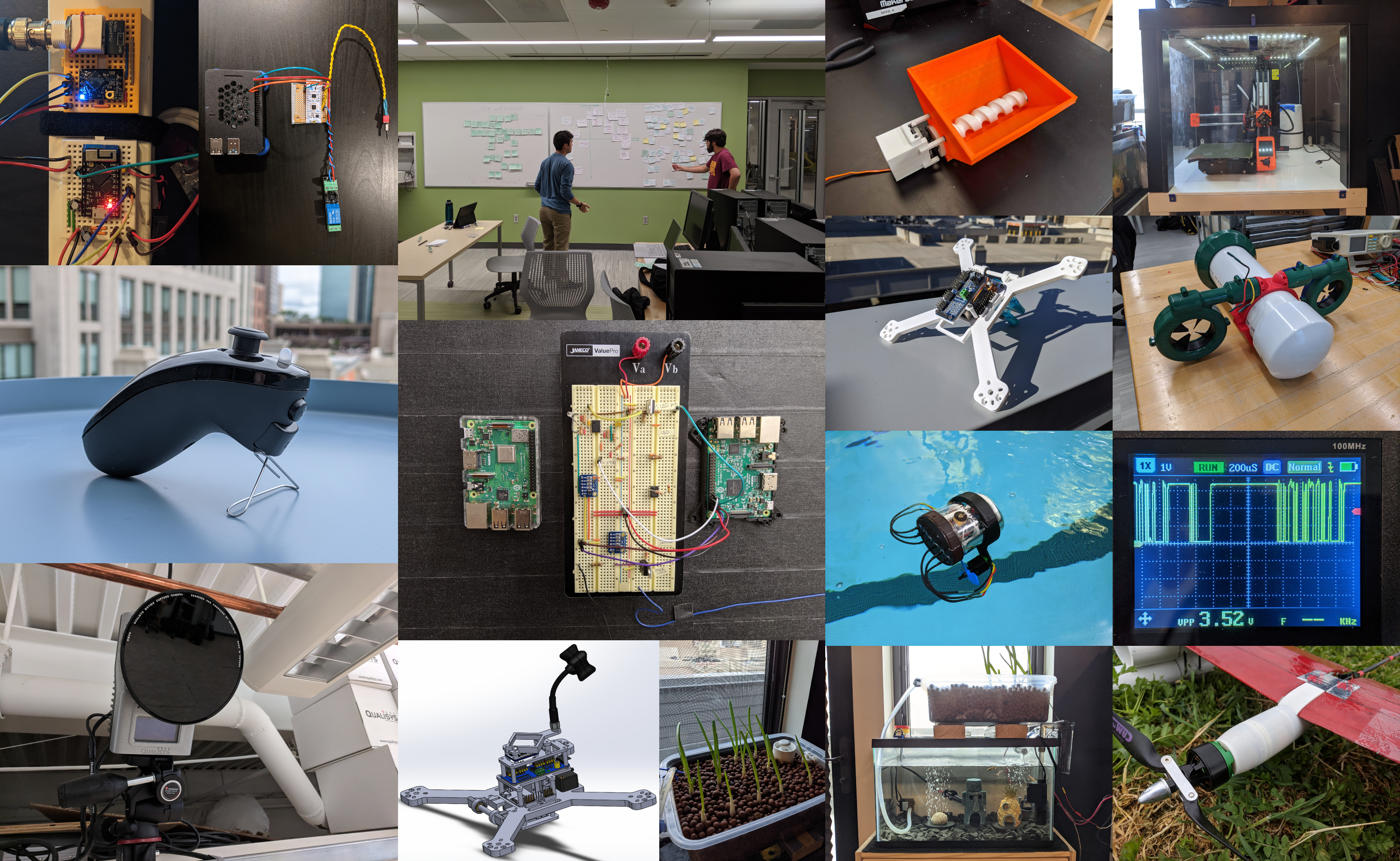

I graduated from Union College in June 2020 with a B.S. in Computer Engineering. I greatly enjoyed learning the principles of research, design and implementation and continue to apply an engineer's mindset wherever I can. I have experience in a variety of areas including but not limited to: machine learning, embedded systems, autonomous vehicles and full-stack development.
During my freshman year at Union College I joined the AERO club, a student-led organization that builds an RC airplane every year for a nation-wide design competition. During my time with this club I held multiple positions including Secretary, Head of PR and eventually Electronics Pod Chief Engineer. Over the years we placed several times, including first place for flight score amongst all US teams and third place overall.
During my sophomore year I joined a research group that focused on classifying the behavior of a vibrational tensegrity robot. I co-authored a research paper on the subject which was accepted to the 2020 IEEE Symposium Series on Computational Intelligence (SSCI). During that time I also managed our Qualisys Motion Capture System (received from an NSF grant) and taught technical and non-technical students alike how it could be used for their interdisciplinary projects.
This portfolio documents past and present projects I have worked on through research groups, engineering teams and in most cases, personal interest. I'm always looking for new projects and usually have one or more in the works. Due to time constraints, this portfolio may not always be up to date. My Github (linked below) may be a better resource for what I've been working on lately.
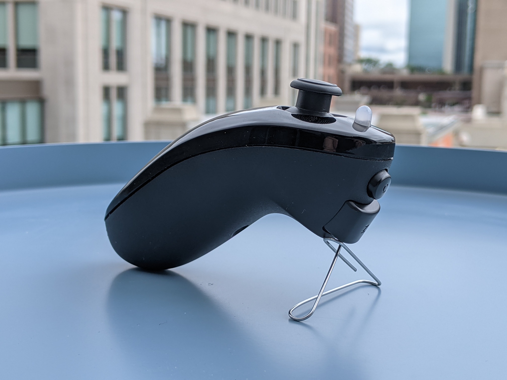

Around June 2021 I discovered Tensorflow Lite for Microcontrollers and decided to start a project based on their stack. I also found out that a Nintendo nunchuk uses the common I2C protocol to communicate, and realized a nunchuk's joystick could be used to "draw" 2D shapes that could be classified as commands by a convolutional neural network (CNN).
Source code, build instructions and CAD files can be found on Github. This webpage describes the design process.
Convert a Nintendo nunchuk into a general-purpose input device capable of recognizing commands via joystick gestures. It's main features are:
Use cases include BLE controller, Home Assistant API Client, RC transmitter, etc.

BLE HID demo

Deep Sleep micro USB touchpad wakeup demo
The full parts list w/ links can be found on Github (above link).
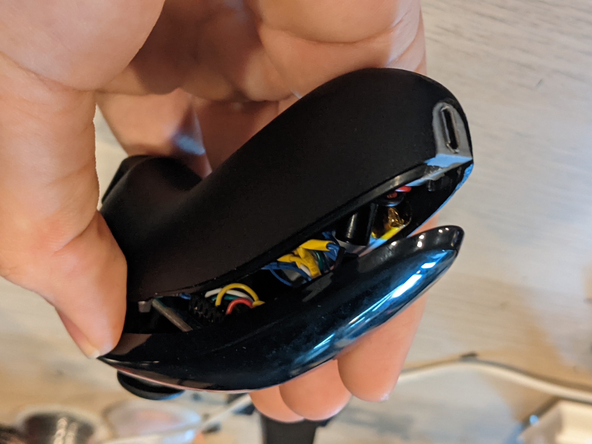
Aside from the MCU, the only component to select was the battery. I chose the largest 1S LiPo I could find that still left enough space for everything else. I also added a single RGB LED to the nunchuk for status indication.
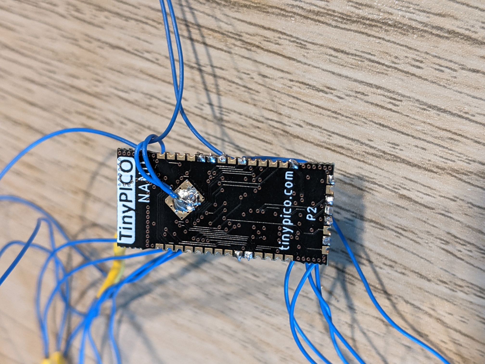
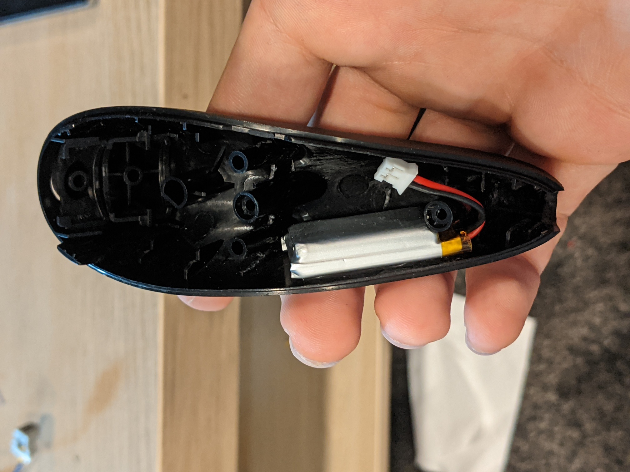
The ESP32 microcontroller was chosen for a few reasons:
I decided to pick a development board as opposed to designing my own due to cost/time. I chose the TinyPICO Nano due to its small form factor, lack of a micro USB port and the fact that it has a 1S LiPo charging circuit built-in.
This section describes the ML model design process. As mentioned, a CNN was chosen for this application. It has an input shape of 16x16x1, prescaled down from the raw joystick shape of 256x256. At the time of writing there are 6 pre-trained gestures:
More gestures can be trained and added to the model, more info in Github.
The CNN performs very well, consistently topping 99% accuracy. The model file is 13KB.
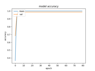
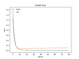

Training demo
A CNN was ultimately chosen to detect joystick commands, however alternate model types were considered. One disadvantage of the CNN is the lack of temporal consideration; for example, there's no way to differentiate between a clockwise and counter-clockwise circle gesture as they both have the same output shape.
A recurrent neural network (RNN) could be used instead to not only record the drawn pixel's coordinates, but also the timestamp. The nunchuk contains an onboard accelerometer which could also be used as input for wand-like gestures. Ultimately this path was not chosen as it was simply out of the project scope.
Future improvements:

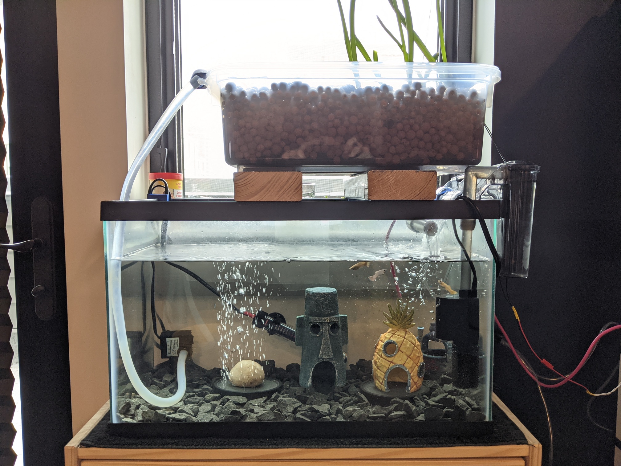
In March 2021 I decided to start an aquaponics system as I was unable to get high quality produce in my local area. In order to adequately attend to this system I developed several control/monitoring solutions to view sensor data and manage water pumps/LEDs/etc. Both the aquaponics system and controllers are described here.
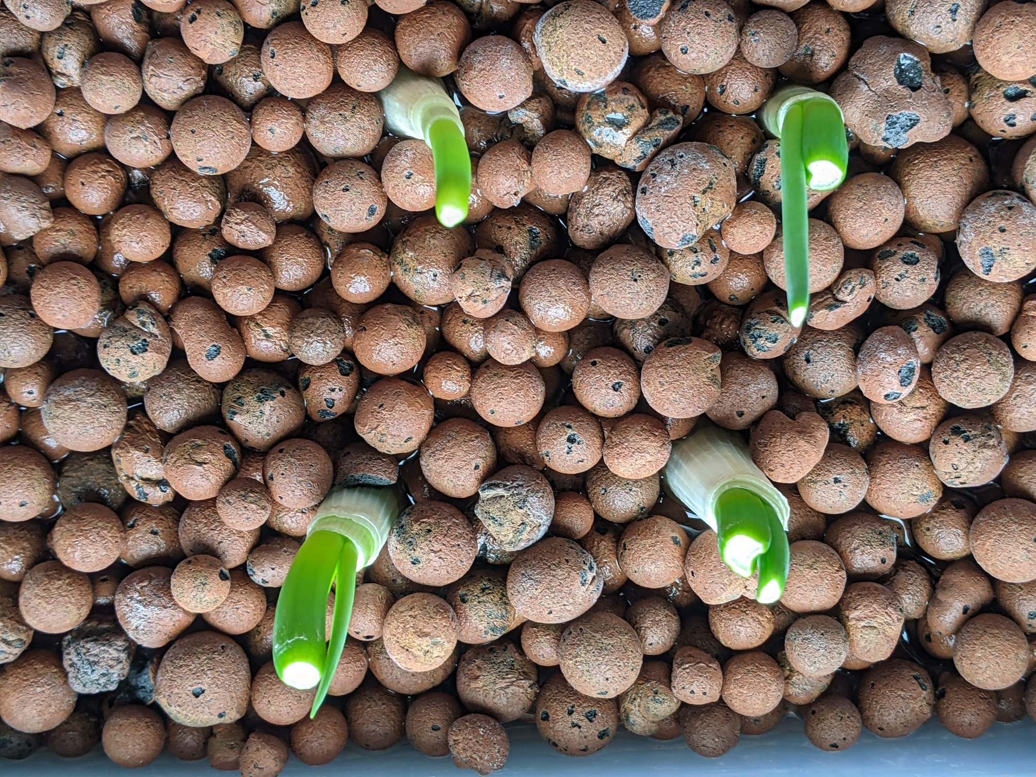

Aquaponics is a combination of soil-less farming (hydroponics) and fish farming (aquaculture). Fish release ammonia-rich waste, bacteria in the tank/grow bed convert it into nitrate, which plants finally absorb as fertilizer. For more information, the Food and Agriculture Organization (FAO) released an excellent guide on small-scall aquaponics systems.
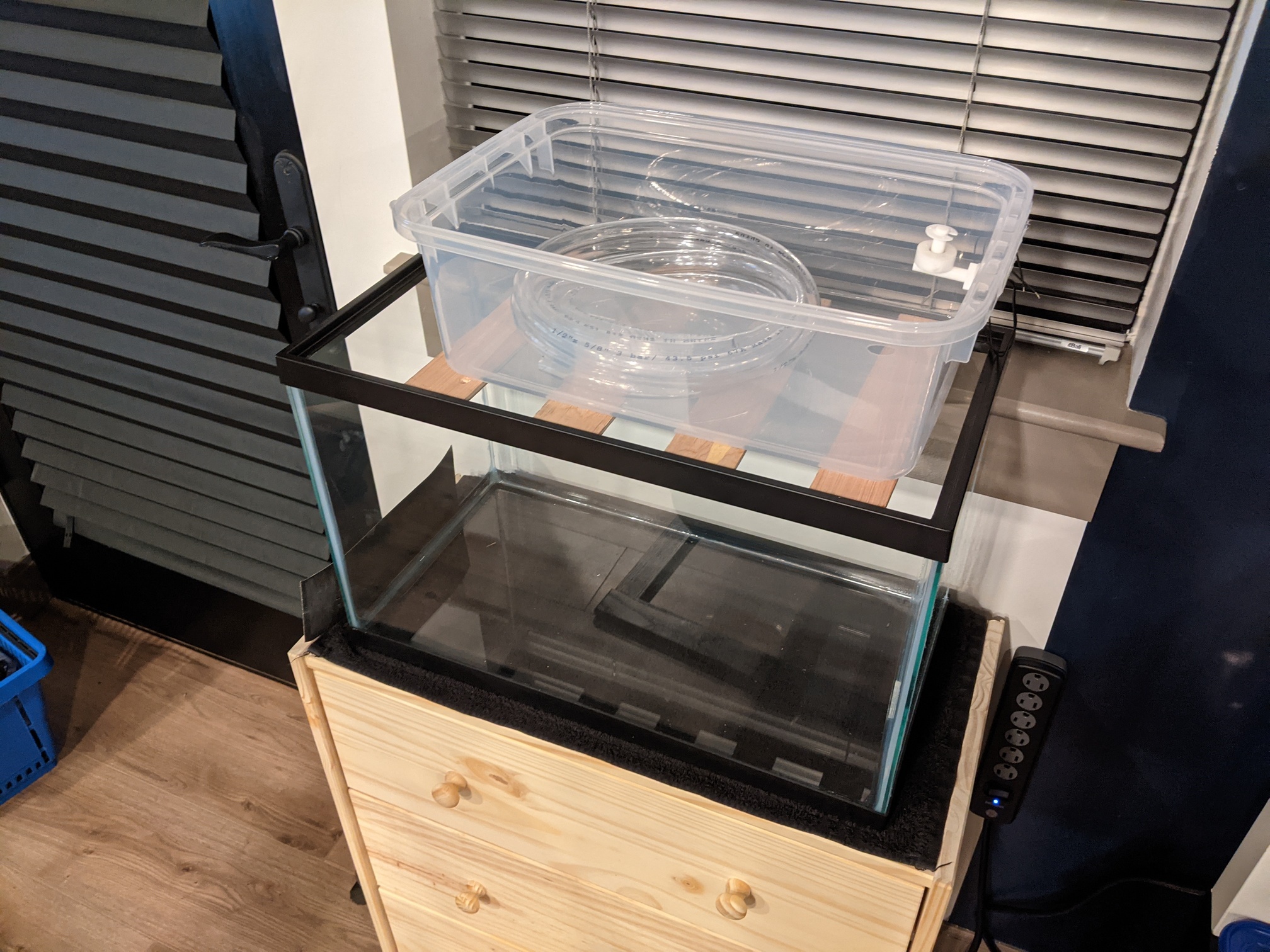
Multiple aquaponics system designs were considered (Deep Water Culture, Nutrient Film Technique) however an 'ebb and flow' system was chosen due to its low cost and space efficiency. As this system was going to be housed in an apartment, these benefits were heavily weighted.
The system specs are:
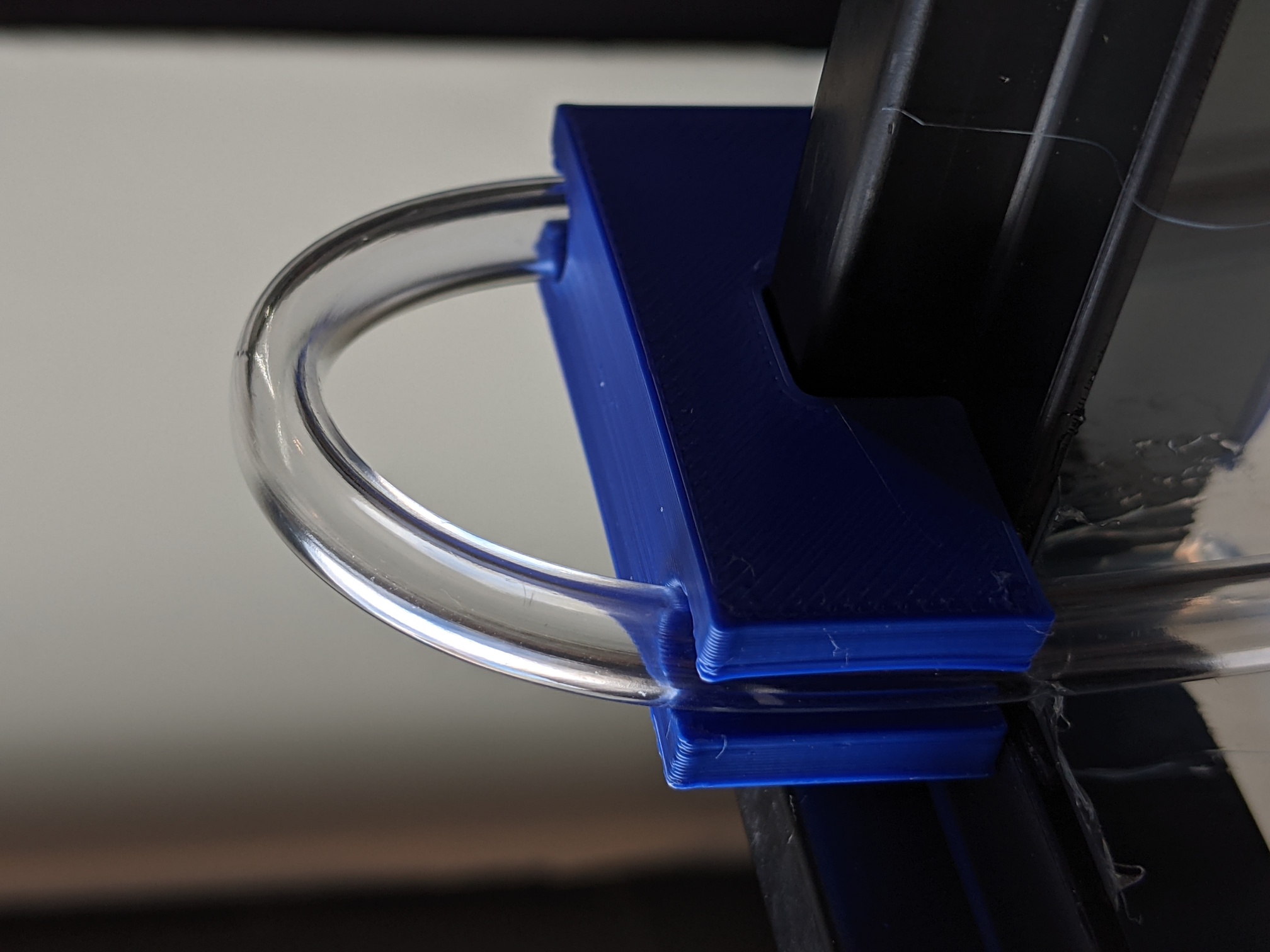
Several small components such as tubing frames and grow bed stand supports were also designed and 3D-printed.
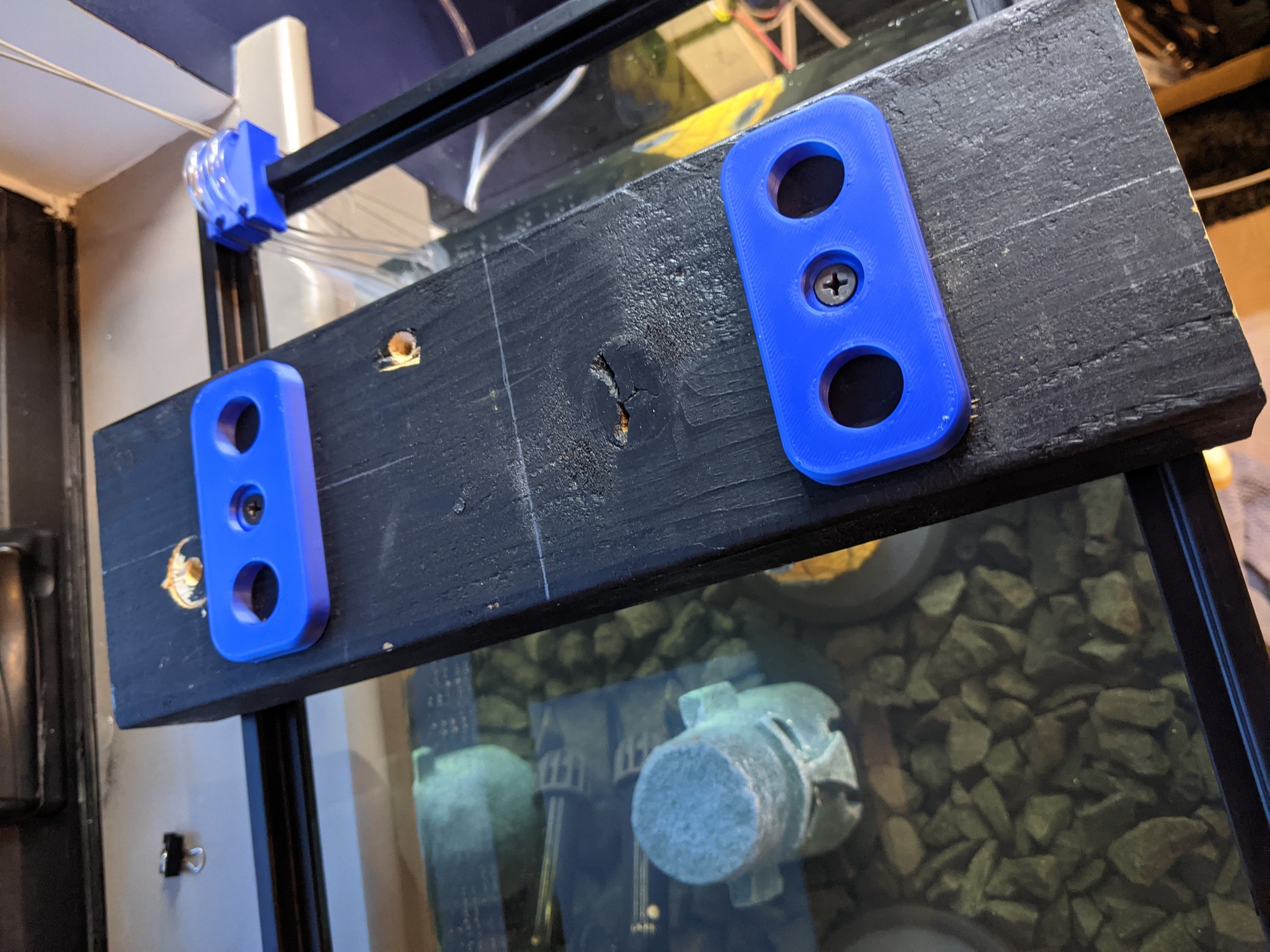
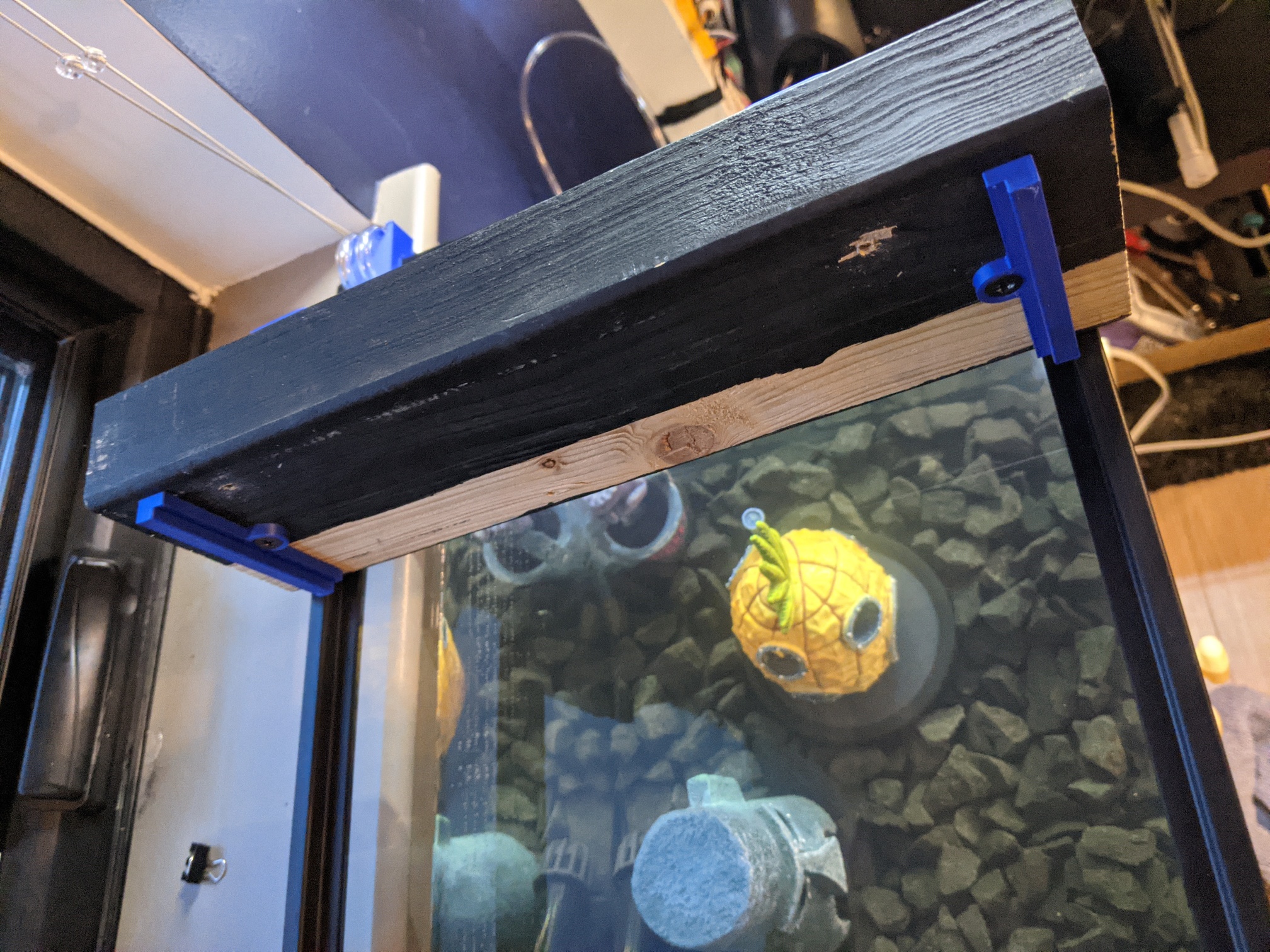
Two controllers were developed over the course of this project, PiPonics and ponics32.
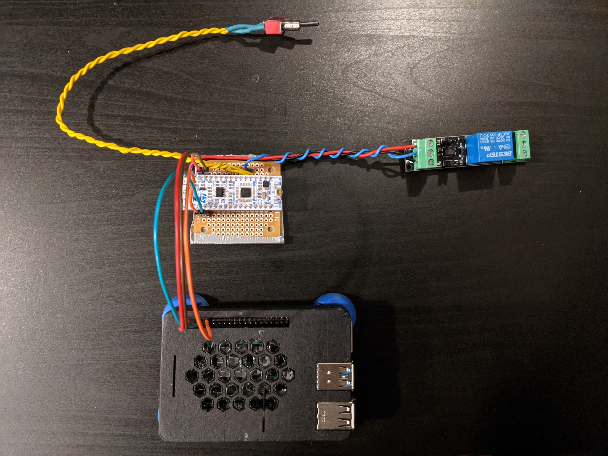
PiPonics is based on a Raspberry Pi 4B and a low-power STM32 board. The Pi runs a full-stack web server and the STM32 interfaces directly with sensors and actuators. The two boards communicate via UART.
ponics32 is based on the ESP32 microcontroller. It houses the web server and sensor/actuator interface tasks on the same board, unlike with PiPonics.
Both controllers are described below.
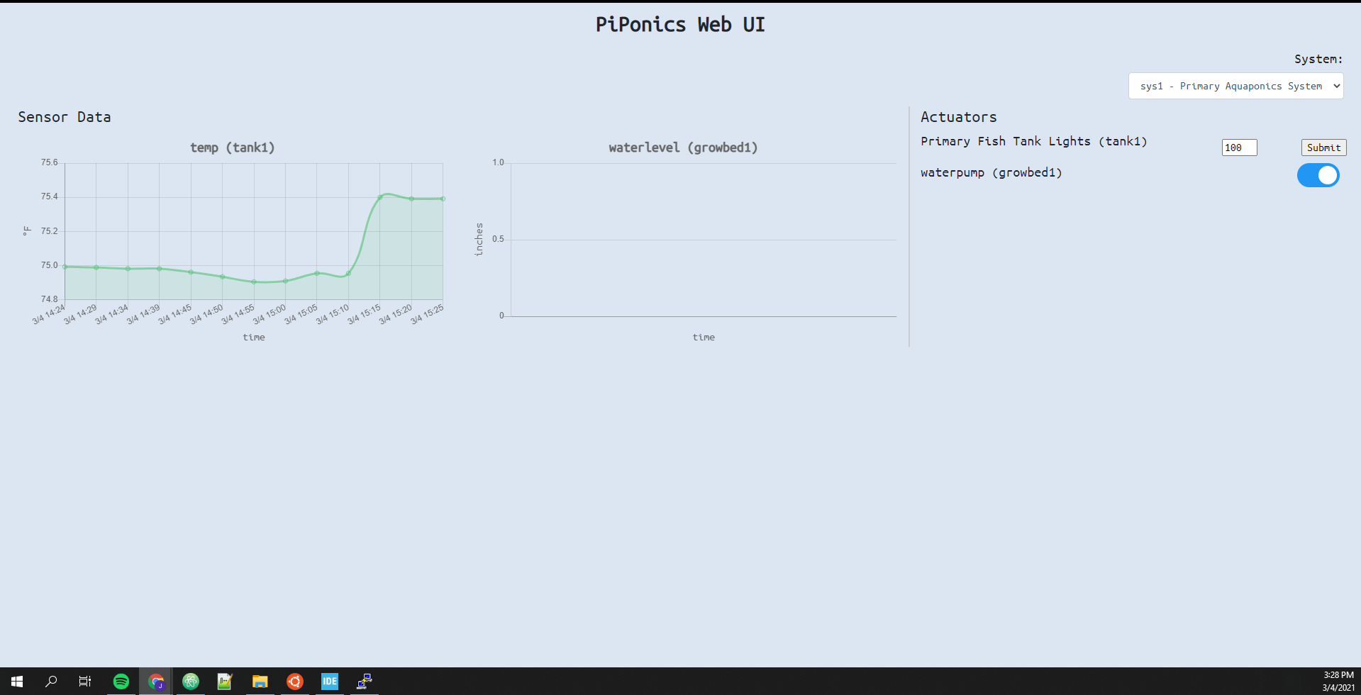
PiPonics is a control & monitoring solution based on the Raspberry Pi and STM32 microcontroller. It's main features are:
PiPonics is built using Docker on the Pi and FreeRTOS on the STM32. Source code for PiPonics can be found here, and source code for the sensor board here.
The purpose of PiPonics was to develop a full-fledged control & monitoring solution for a home aquaponics system I was building. A key design requirement was easy deployment, as I plan to create many more *ponics systems in the future and wanted to minimize configuration time.
The Raspberry Pi runs several docker containers, described in Github (linked above).
A NUCLEO-L432KC board is used as a sensor board in this project, chosen for its low power consumption and compact size.
An Atlas Scientific EZO Temperature Sensor was used to monitor water temp and communicated with the ESP32 via the I2C protocol. Other sensors (pH, conductivity, turbidity) were also considered but ultimately ignored due to their high cost. Further water quality parameters (ammonia, nitrate, nitrite) were recorded through a chemical test kit.
A relay module was used to drive the submersible water pump. The pump is configured to always run unless manually stopped, common for "ebb and flow" aquaponics systems.
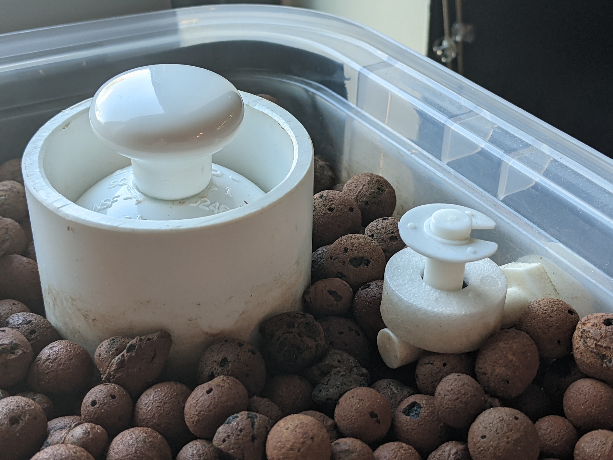
Two emergency features were introduced to avoid spillage:
The primary goal of this project was to create an easily deployable monitoring solution. The "single configuration file" principle works well on the Pi- database and frontend and initialized according to the system defined in that config file.
However, there is some repeated logic between the STM32 board and the Pi during sensor/actuator id resolution, defeating the "plug-and-play" aspect. A solution to this issue is to send the system definition to the sensor board at startup (including pin assignments on the STM32).
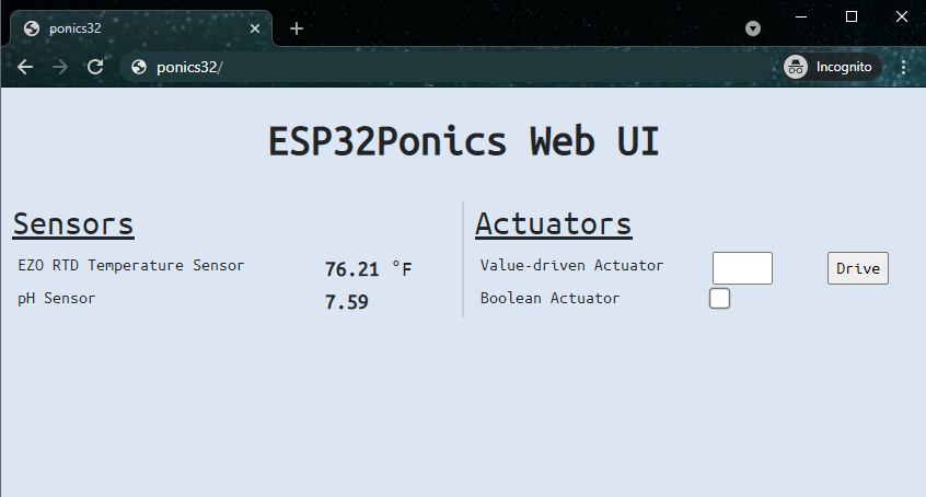
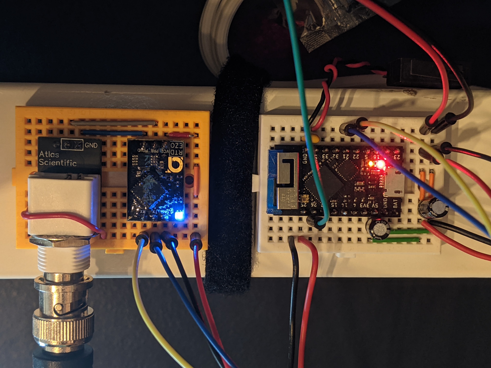
ponics32 is an ESP32-based control & monitoring solution designed for home aquaponics/hydroponics systems. It's main features are:
ponics32 is built using Espressif's IoT Development Framework (ESP-IDF). All source code, build and flash instructions can be found on Github.
The purpose of ponics32 was to address the shortcomings of the previous control/monitoring server. Where PiPonics is unportable and flashy, ponics32 is robust and simple: rather than use a second board to interface with sensors, the ESP32 has the peripherals and compute power to both collect data and display it.
As alluded to earlier, a ponics32 system consists of sensors, actuators, and emergencies.
The Atlas Scientific temp. sensor and submersible water pump used in the PiPonics project are reused here.
An emergency is also defined for this system to detect grow bed water overflow using a float switch. If the water level rises too high, perhaps due to a siphon clog, the float switch is triggered and the water pump is automatically shut off.
There are a plethora of monitoring solutions already; ESPHome, native to the ESP8266/ESP32 suite of microcontrollers, is an example. While I designed ponics32 to be extensible, it is unlikely it will ever have the features or support that ESPHome offers. Nevertheless, ponics32 does provide an auto-managed frontend web UI and backend support for automatic data collection, and thus may be useful as a framework for testing embedded device drivers in the future.
As always there are a number of improvements that can be made:

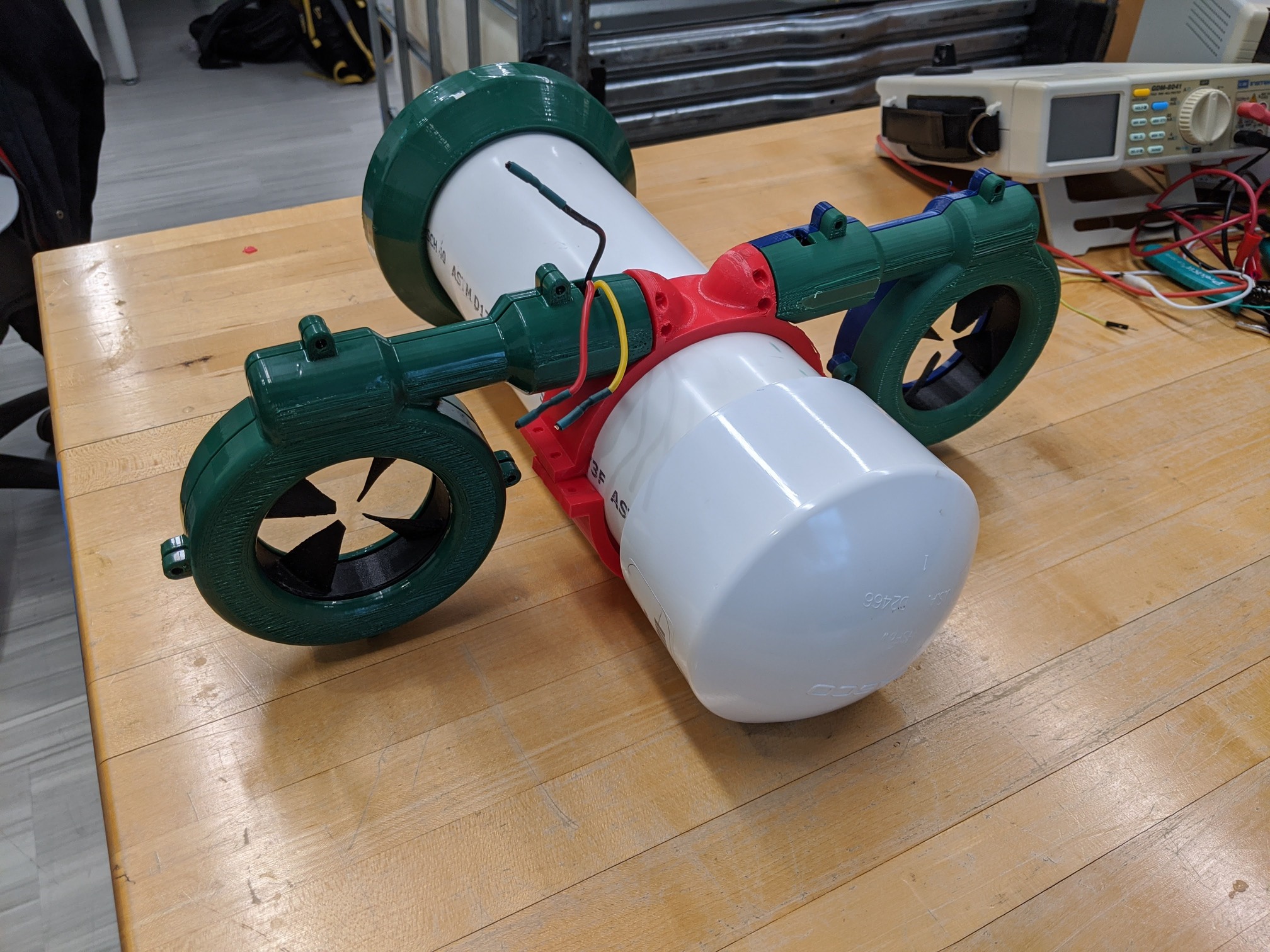
For my senior capstone project I elected to team up with another computer engineer (Xavier Quinn) and two mechnaical engineers (Alexander Pradhan and Samuel Veith) to develop a micro-scale submarine. We worked on this project for a total of three trimesters, one spent on design and two for implementation.
Our project is the Autonomous Flocking µSub Project, or the AFµS Project.
This section summarizes our design approach and key findings. For a more detailed write-up you can read our extensive design report.
Underwater exploration is a challenging and time-consuming task; even today only about 5% of ocean basins have been explored. Common methods include the use of research vessels, stationary sensor networks, and remotely operated vehicles (ROVs), however these methods are either too expensive, slow, or require human intervention and thus doesn't scale.
One solution is the use of Autonomous Underwater Vehicles (AUVs), submersibles capable of performing some decision making along its journey. However, these systems are still very expensive and difficult to manage due to their weight/size.
Finally enter micro-scale AUVs, often only a few feet in length and easily manageable by a single person. Faster, cheaper, more autonomous and manageable than other technologies available, these systems may be deployable at scale.
The goal of this project was to develop an AUV with flocking capabilities for under $500. Unlike existing micro AUVs on the market (which typically cost tens of thousands of dollars), we aimed to create an affordable product that could be used by universities, small research groups or even individuals.
Flocking was added as a design requirement to increase the applicability of this product. According to the the user's budget, multiple subs can be used together to decrease the overall mission time and increase data redundancy and accuracy.
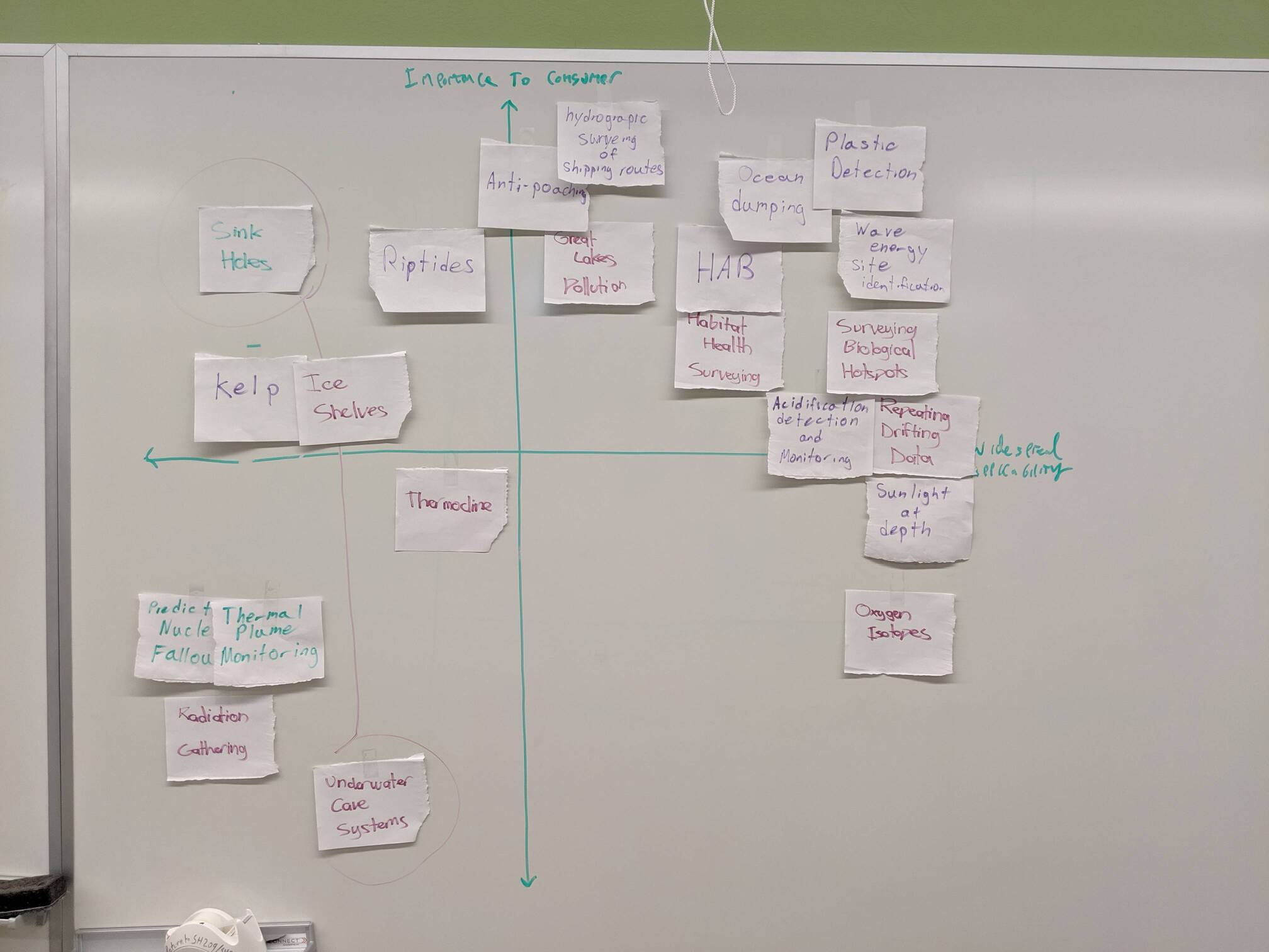
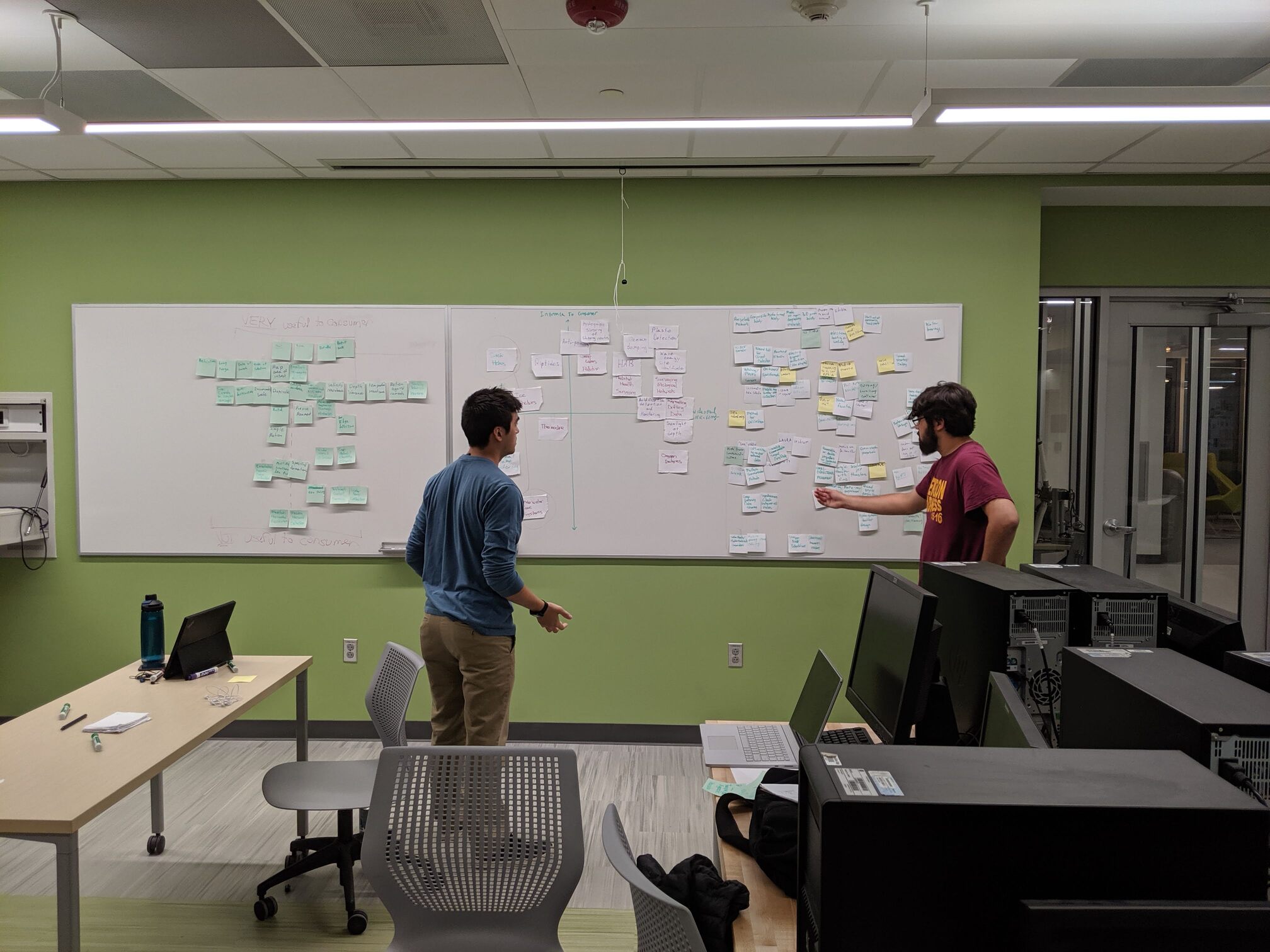
Our team first held several ideation sessions to determine what features our target audience would find useful. We concluded it would be most prudent to focus on more common use cases such as surveying ocean dumping patterns, finding biological hotspots or identifying Harmful Algal Blooms (HABs).
As mechanical engineering capstone projects were one trimester behind ours, we decided there must always be a working iteration of the sub (minimum viable product approach) to ensure both ME and CpE development could take place concurrently. We called these test subs AFµS Test Systems, or ATS's. Isolated testing rigs were also developed for key subsystems.
My work focused on locomotion and inter-flock communication, described below.
Here, locomotion refers to the control system used to drive the sub. Control systems for AUV's are vast and typically specific to an actuator layout/configuration. One of the primary challenges was designing a control system while the mechanical engineering team were still designing the physical system layout.
The "classic" approach of developing control systems involves characterizing the interactions between mechanical drive components and the environment it operates in. It was quickly determined this would entail enough design/development work for a thesis project of its own, and therefore a more practical approach was taken for the sake of time.
Due to our minimum viable product approach, we had a very simple test sub, the ATS Mk. I, which was capable of 2D movement. I decided to start with implementing a standard PID controller for heading change as they have been deployed successfully in non-deterministic environments (i.e. quadcopter auto-stabilization). Based on its performance, we would then decide if alternatives must be considered.
In addition to heading, linear movement is another controls problem. Concurrent research was performed by the other computer engineer to determine if using an IMU-based approach to localization would be accurate enough to feasibly use as reference for movement. If it proved ineffective, our plan was to use periodic resurfacings to gather GPS data and adjust course if need be.
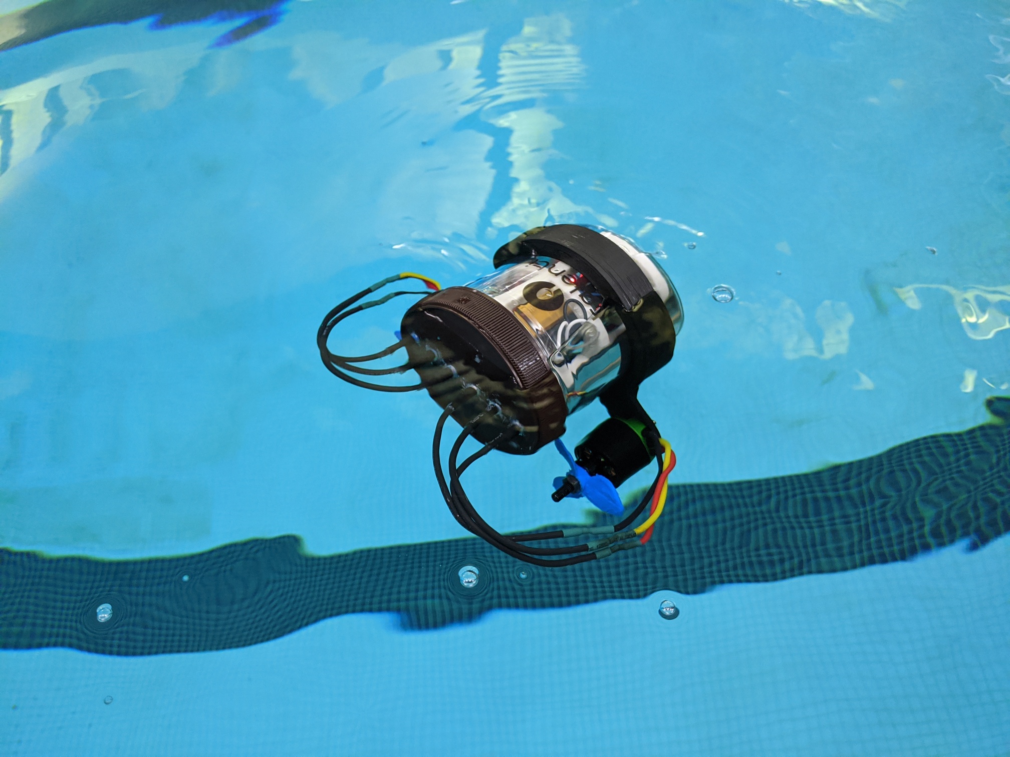
I settled on manual PID tuning as data collection was relatively quick. On average, the ATS Mk. I was able to reach its target heading in under 4 seconds. The Mk. I was fitted with two 30A brushless DC motors which was overly powerful given the sub's size- the Mk. I often overshot its target heading and had to backtrack even with short pulses. It was believed that a sub with appropriately proportioned motors, such as those outfitted on the Mk. II, would perform even better.
With a proof-of-concept that a PID could feasibly be used for target heading, I decided to focus on inter-flock communication while the mechanical engineers completed the design for the ATS Mk. II, which would support 3D motion. This would be the main focus of the last term of capstone development, but unfortunately work stopped here due to the COVID-19 pandemic.
The tried-and-true method of wireless underwater communication is sonar, however it suffers from issues such as high noise and low bitrate. Typical RF communication is possible but suffers from severe attenuation with water as a transmission channel.
A third emerging option is underwater wireless optical communication (UWOC), which uses high power LEDs to transmit information. This method allows for high bitrates in a relatively low noise environment. UWOC was chosen for inter-flock communication.
UWOC still suffers from attenuation underwater, which varies according to wavelength. This also varies with salinity; wavelengths of ~500nm (blue) attenuate the least in ocean water, while wavelengths of ~600nm (yellow) attenuate the least in freshwater. As we intended to use the sub in both, we settled on a wavelength of ~567nm (lime). While range may be reduced in some cases, reusability is preserved.
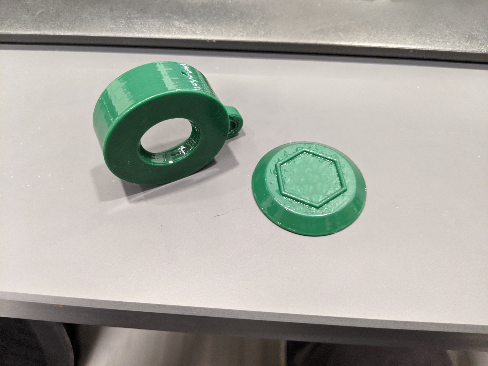
The chosen modulation method was pulse-position modulation (PPM) with a periodic clocking pulse. PPM is well-suited for optical communication systems due to low propagation delays and little multipath interference.
The clocking pulse was added to reduce the possibility of incorrectly decoding the data due to synchronization issues. As we didn't have the budget for high-precision atomic clocks, this method allowed for accurate timing regardless of how long the sub has been active.
It should be mentioned that a common solution to syncrhonization in PPM systems is a method called differential PPM, or D-PPM, where each pulse delay is measured relative to the previous pulse, not the period start. This method was primarily overlooked because it results in variable data frame lengths and using fixed frame lengths aids in error detection.
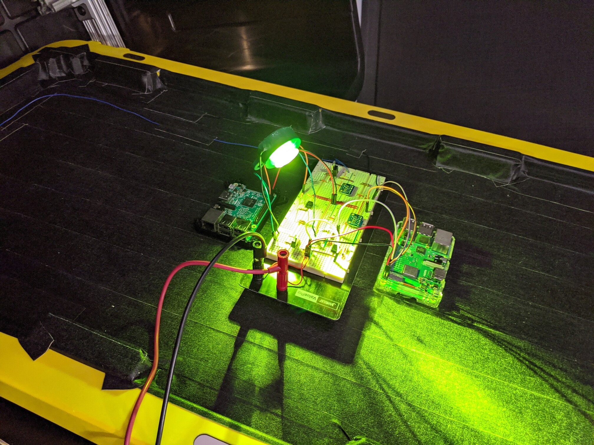
The transmitter consists of a MOSFET switching circuit driving a high power LED and the receiver consists of a biased phototransistor connected to an op-amp comparator. Tests were first performed in air to verify the implemented communication protocol. It became clear that passing our benchmarks w.r.t. bitrate wouldn't be difficult so I focused on characterizing environmental conditions that would prevent reliable communication and exploring potential solutions.
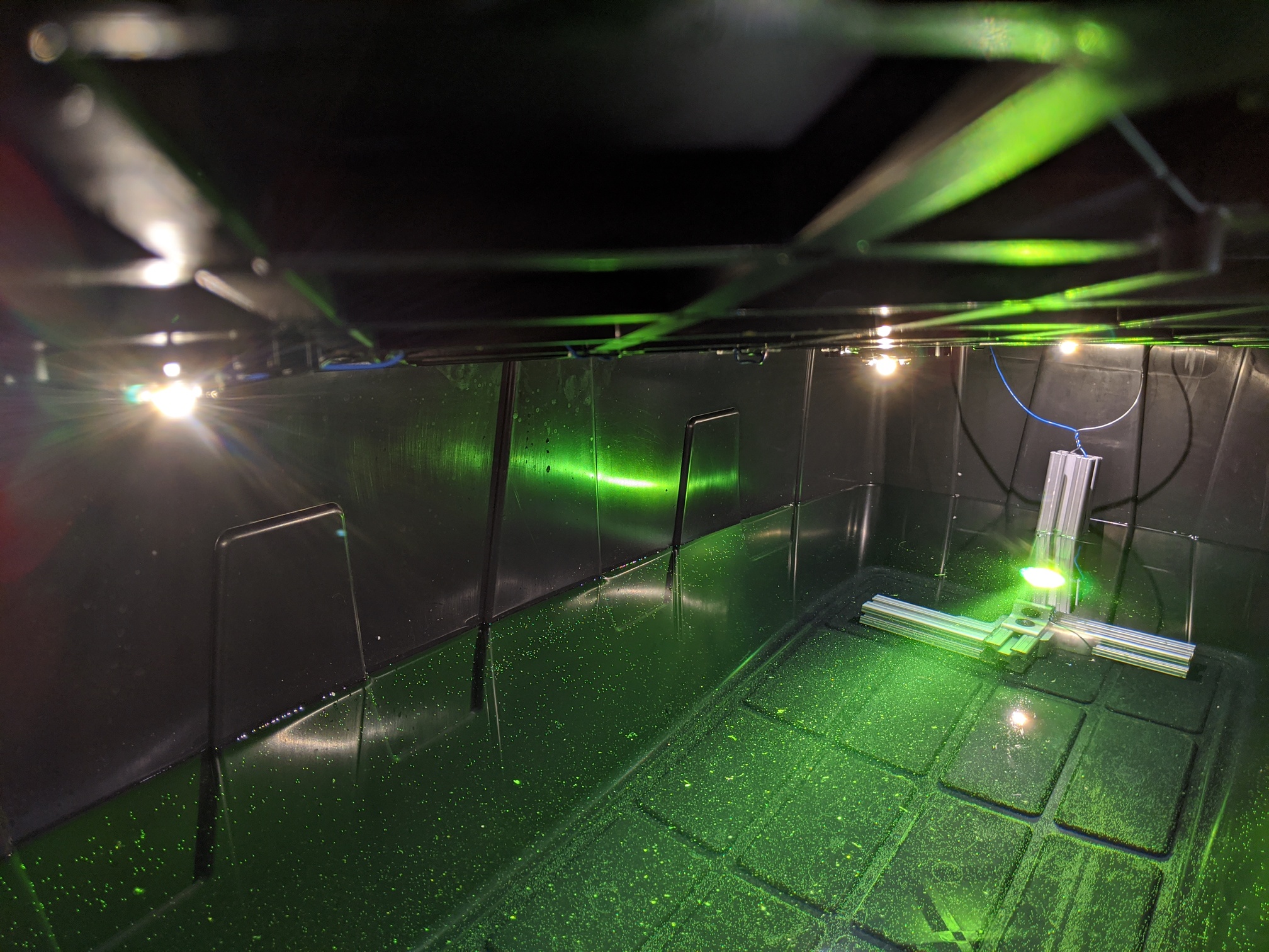
I designed a test rig with ambient light control as identifying the noise floor was a key challenge. On the receiver side, one of the comparator inputs is connected to the phototransistor and the other to a voltage level that (ideally) prevents the comparator from firing due to ambient noise but still receives UWOC frames. The goal of these tests was to identify what that voltage level was.
I determined that while the communication system could be used in various ambient lighting conditions, there wasn't one single comparator voltage level that could be used to attain an acceptable BER. Therefore some method of identifying the noise floor and adjusting the receiver sensitivity accordingly was necessary. Rather than using a set voltage, a digital-analog converter (DAC) was added to dynamically set the voltage level.
I chose to record the full set of phototransistor voltages according to ambient light levels in the tank to determine what the minimum comparator voltage would be required at that illuminance level. This resulted in a simple lookup table which allowed for quick response to environmental changes with a low computational overhead. With this method in place it was possible to adjust the phototransistor sensitivity automatically and attain better BER's.
Unfortunately due to the COVID-19 pandemic, research ended at this point.
Unfortunately due to the COVID-19 pandemic we lost access to our lab equipment and space, and thus the AFµS project ended a trimester early.

Back in 2018, Union College was offering Presidential Green Grants for students with projects aiding in sustainability efforts. Several other students and I decided to write a proposal for an aquaponics system that could be deployed in disaster-stricken areas as a means for an immediate food supply.
Aquaponics is a combination of soil-less farming (hydroponics) and fish farming (aquaculture). Fish release ammonia-rich waste, bacteria in the tank/grow bed convert it into nitrate, which plants finally absorb as fertilizer. For more information, the Food and Agriculture Organization (FAO) released an excellent guide on small-scall aquaponics systems.
Develop an aquaponics system that is scalable, easy to use, and as autonomous as possible for deployment in disaster-stricken areas. While aquaponics systems are expensive to set up initially, the time and financial cost of maintaining them is relatively low, making them ideal for applications such as this.
A long-term goal for the project was to use Black Soldier Fly Larvae (BSFL) as a food source for the fish. BSFL survive on compost and due to a genetic quirk, always climb to the largest point in whatever container they're in. Determining an appropriate feeding rate and positioning the BSFL container over the fish tank would theoretically mean that the only input this system requires is compost, increasing its sustainability.
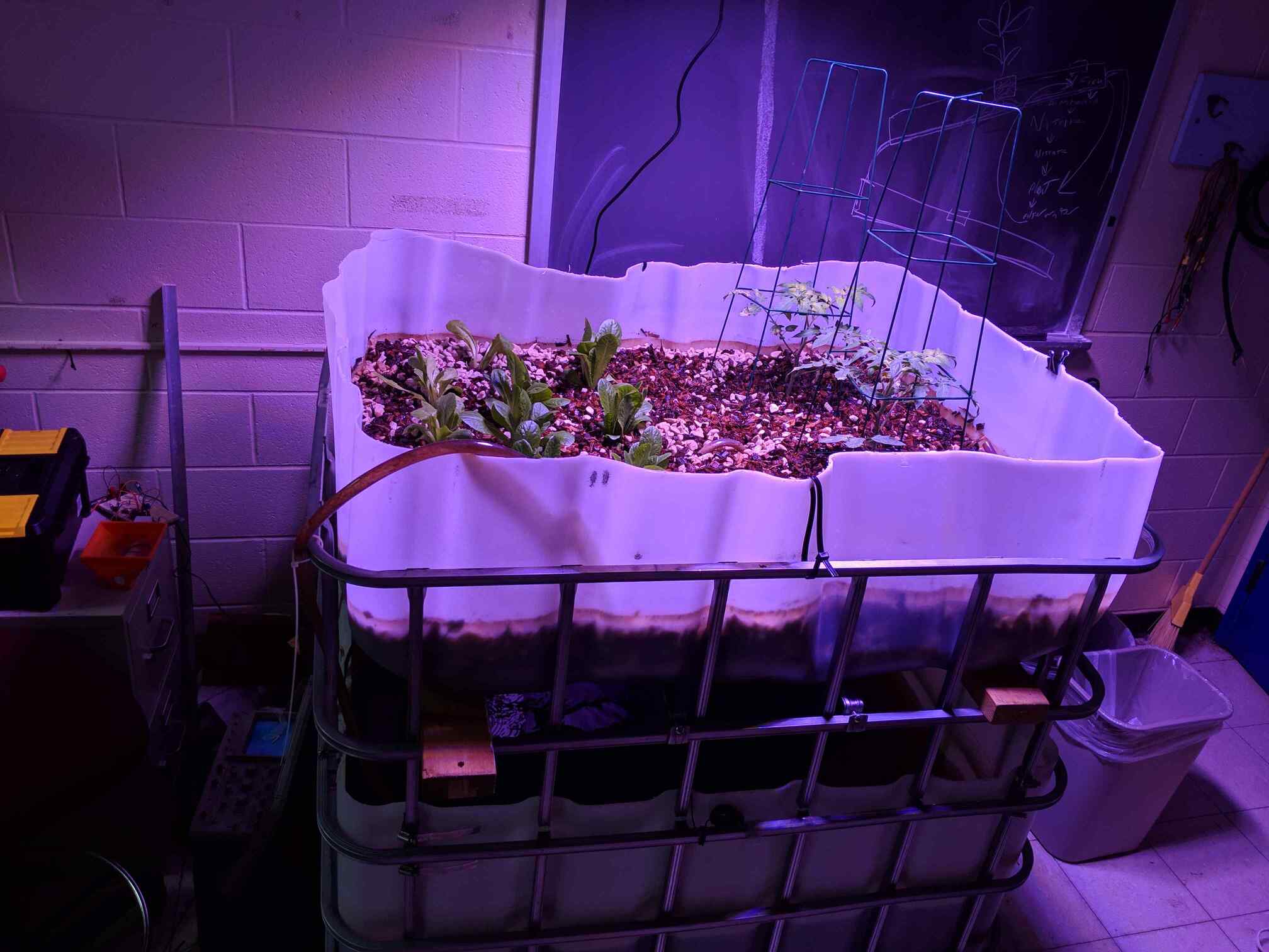
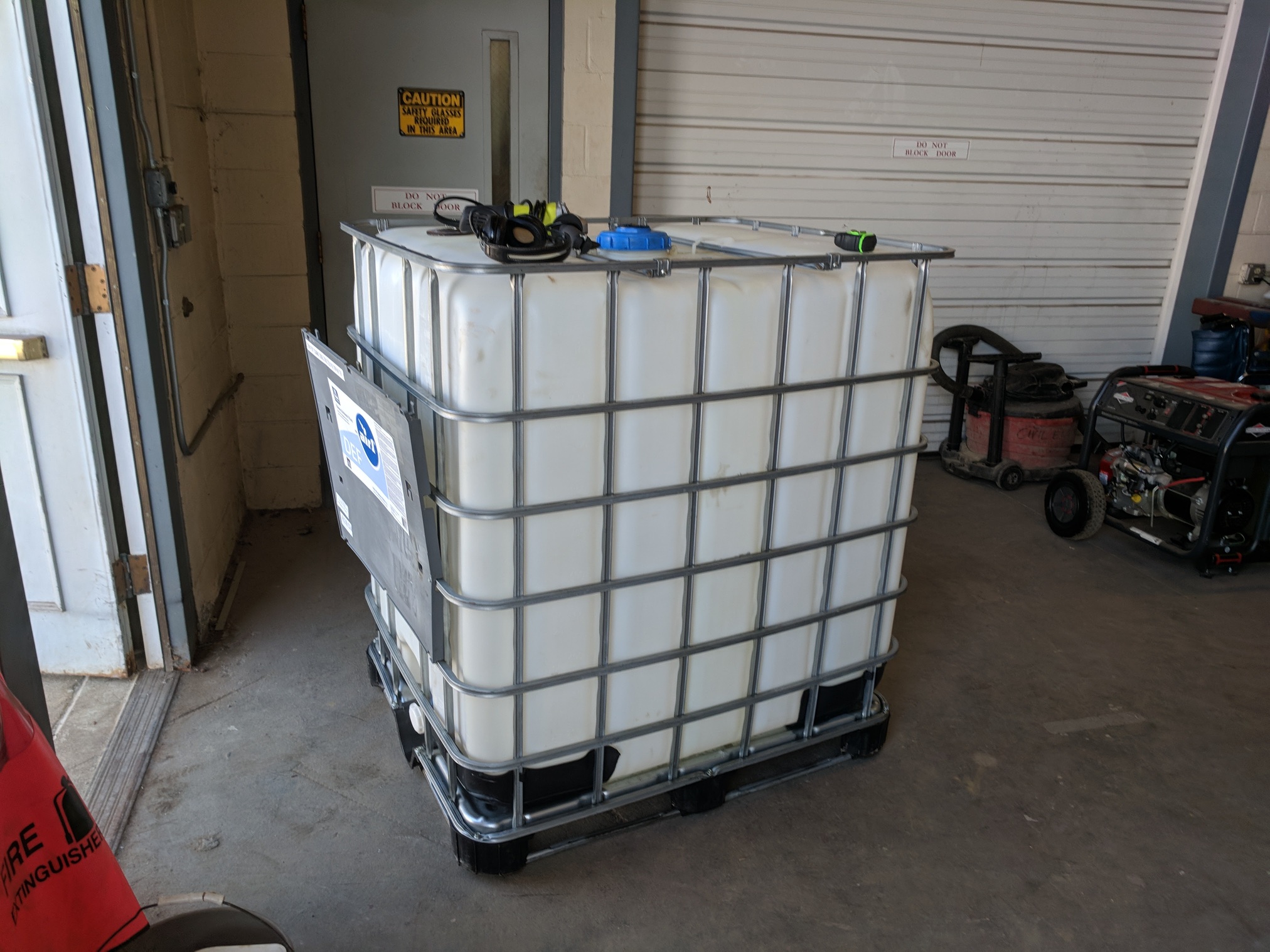
We found a used IBC tank to use for our system. After converting the top to a grow bed, the tank was filled with water and ammonia was introduced to start the nitrification process. At this point we left for summer break and returned several months later to a ready tank.
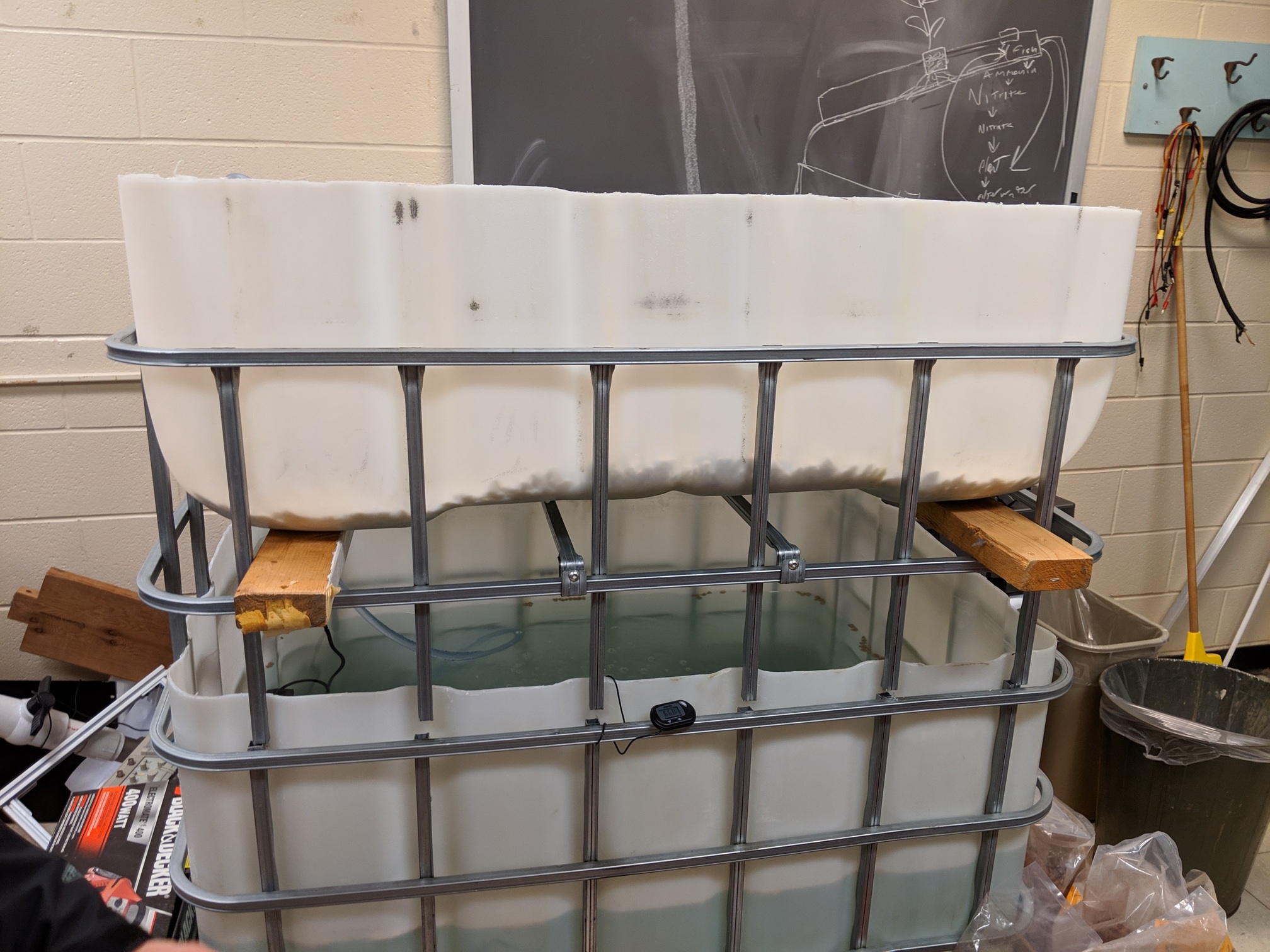
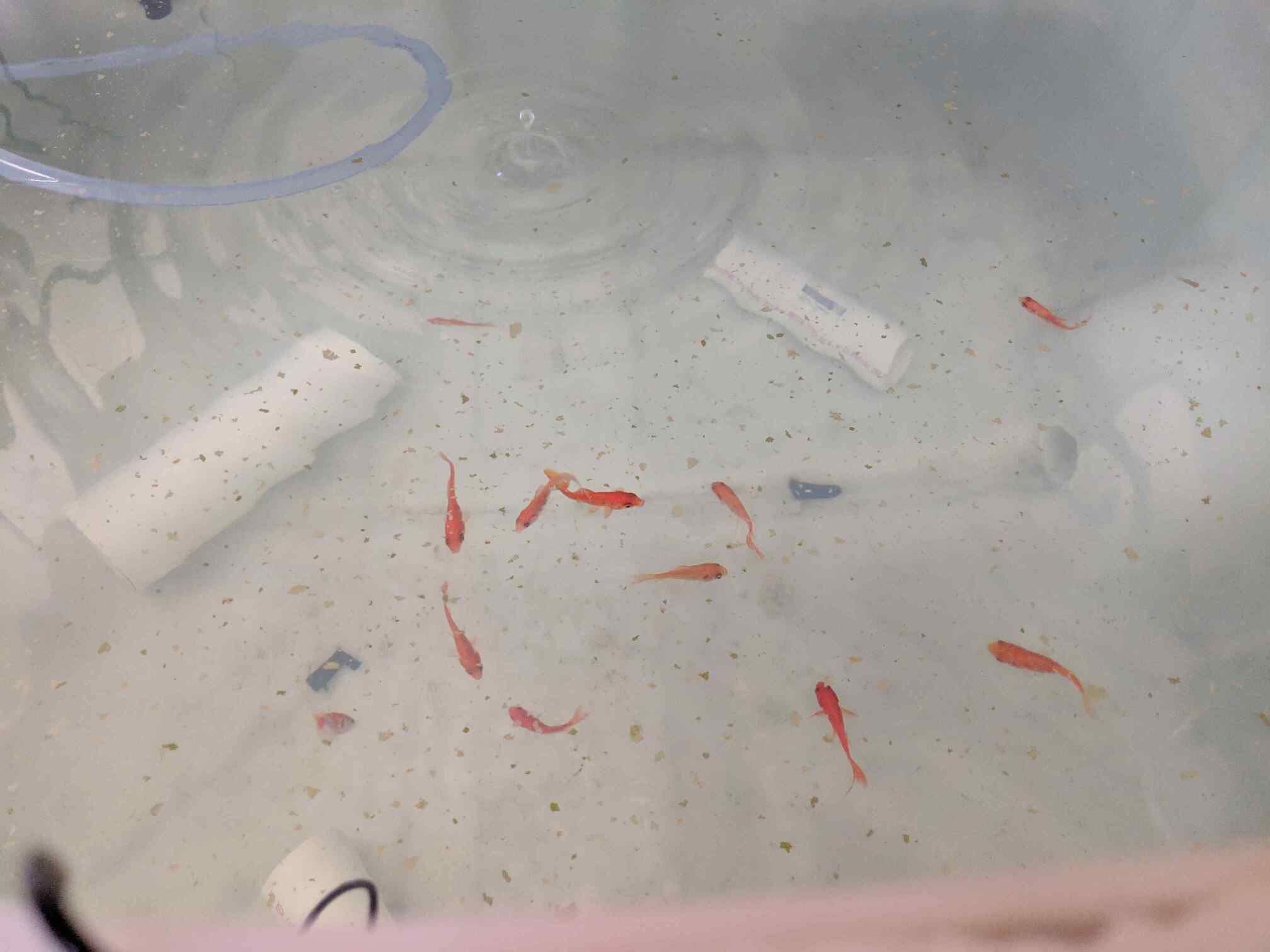
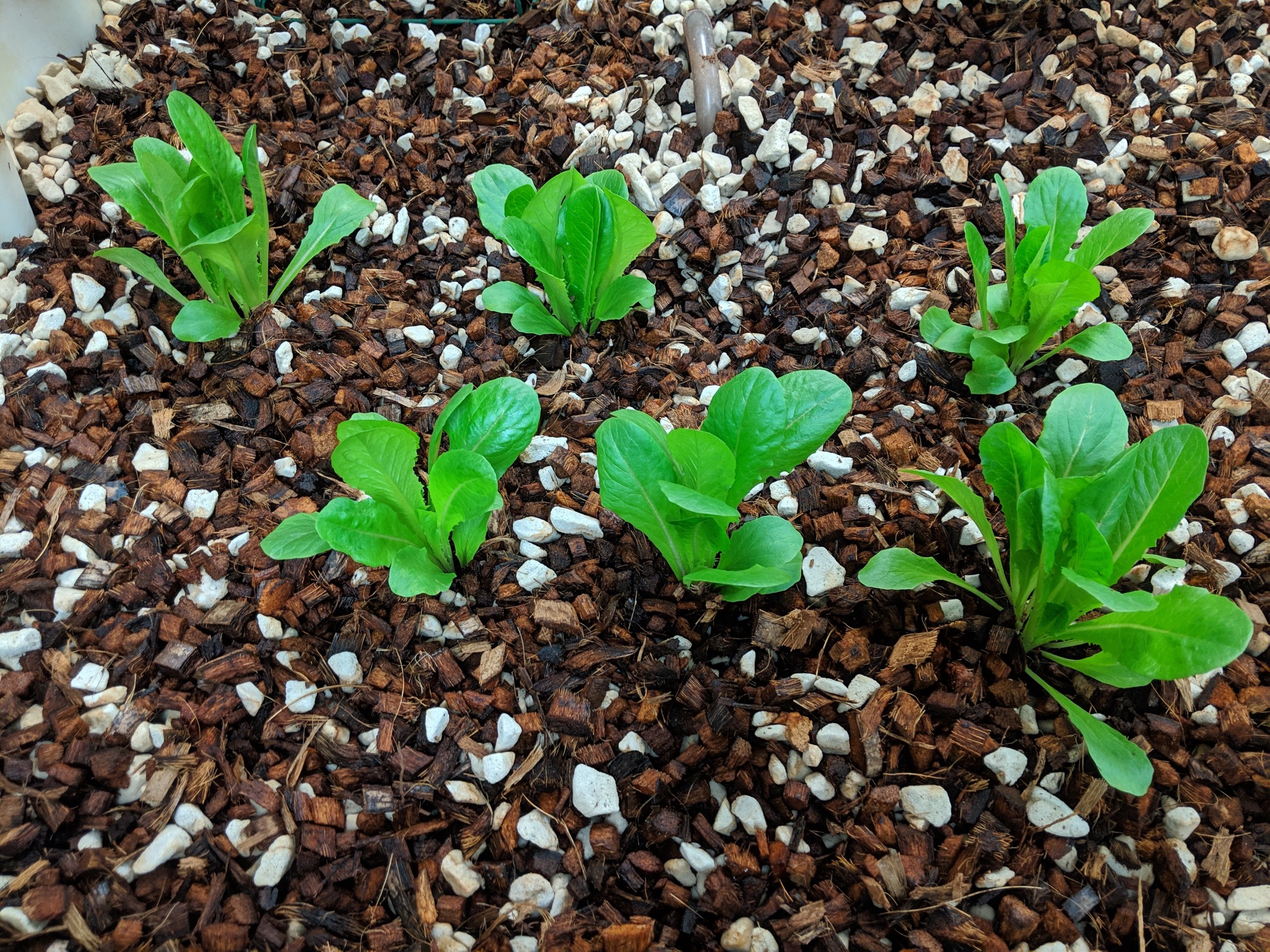
Over the next few terms we selected grow medium, populated the fish tank with feeder fish and added tomatoes and lettuce. Our work then mostly focused on tuning water quality parameters and maximizing produce output.
For a class in embedded systems a fellow computer engineer and I designed a 3D-printed automatic fish feeder running off a PIC24 microcontroller that was used in this system.
In 2020, work on this project was halted due to the COVID-19 pandemic. I've developed other aquaponics systems since, which can be found in this portfolio.

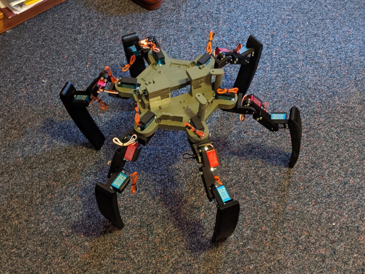
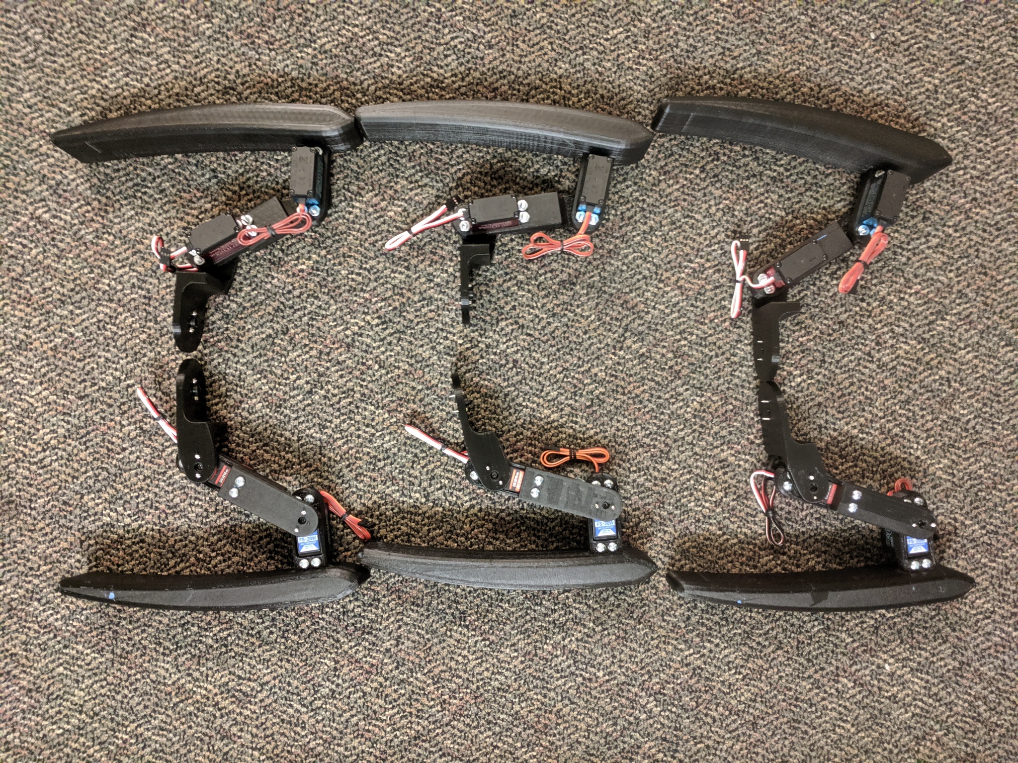
At Union College I lived in an off-campus house called Tech House. We had an operating budget for events and projects we could show to the student body. During my senior year my fellow housemates and I decided to spend our budget to design and develop a hexapod, which we would assemble and test through a house event.
The goal was to develop a hexapod capable of basic motion and obstacle avoidance given our limited budget. Ideally it could both be controlled directly like an RC vehicle or move autonomously.
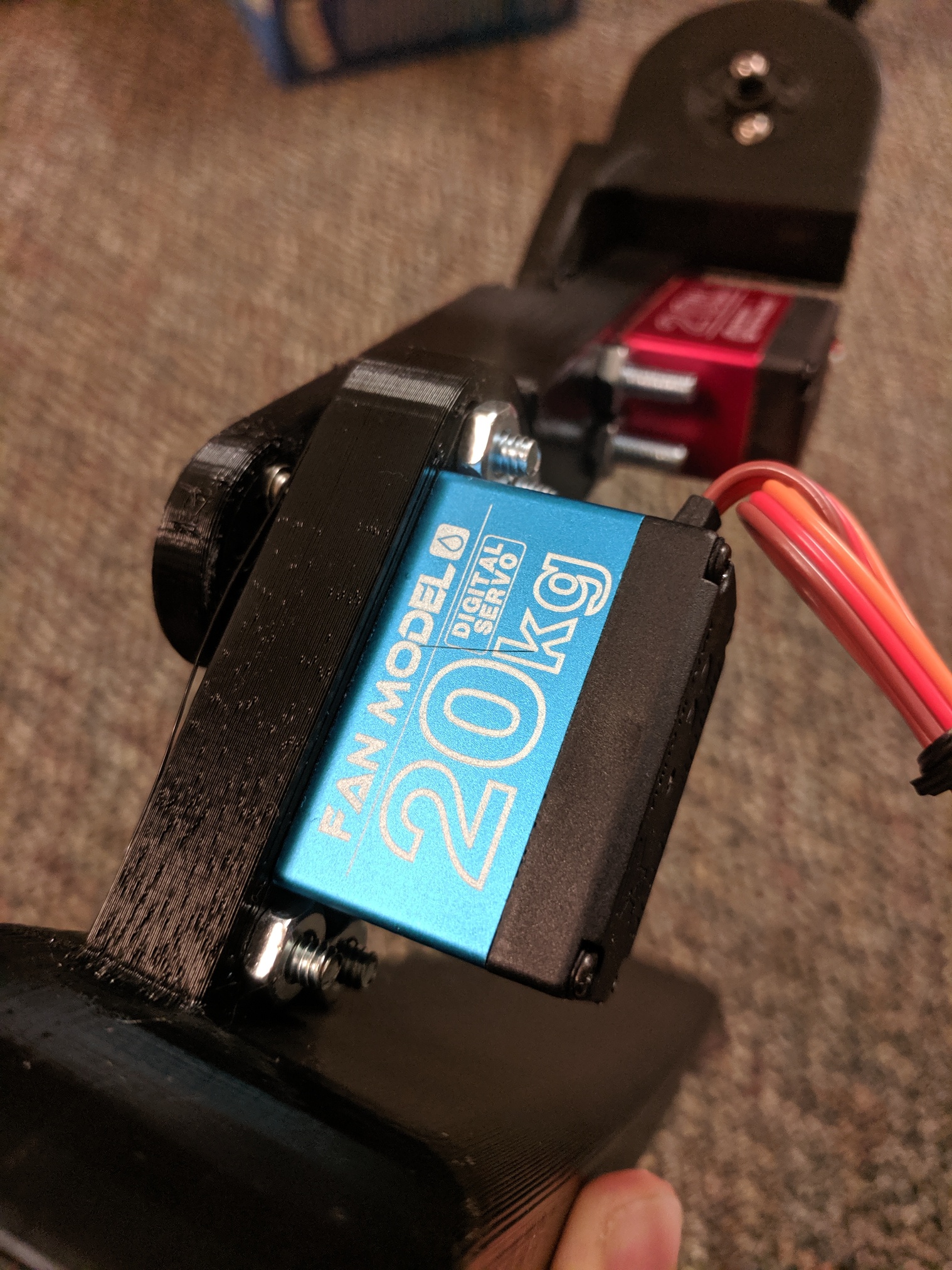
One of the mechanical engineers living in Tech House at the time, Alex Pradhan, designed the physical system which were then 3D-printed. 20kg servos were chosen for the joints. Ultrasonic rangefinders were added to the main base and a RockPi 4 was chosen as the main SBC.
There were numerous methods of control that we considered. The final plan was to use ROS and its reinforcement learning libraries, possibly in tandem with Union College's motion capture system, to train the hexapod to move.
The physical system is constructed but due to the COVID-19 pandemic we were unable to host the event before being sent off campus.
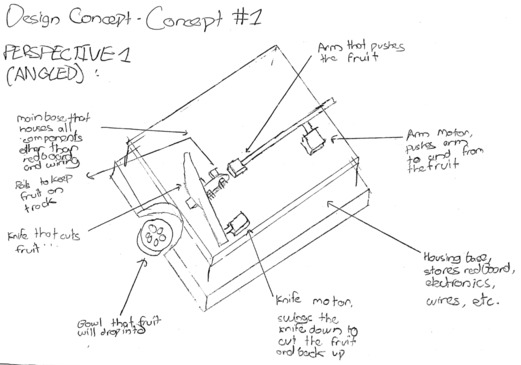
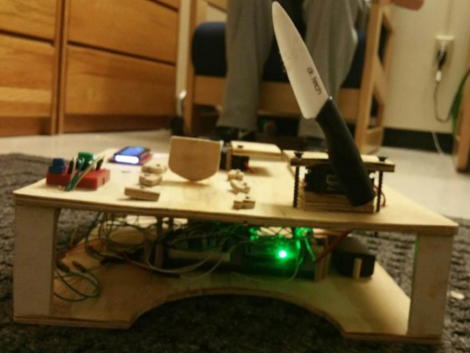
This is my first engineering project, from an introductory engineering class I took fall term, freshman year. We were paired into groups and told to design and implement a project on a Sparkfun RedBoard. My team decided to make an automatic fruit cutting machine.
The goal was to develop a machine that could autonomously cut fruit and deposit it into a serving bowl. Cut size should be an adjustable parameter.
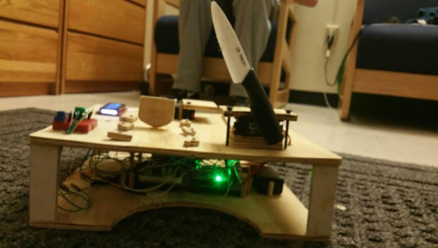
Our electrical design consisted of a continuous rotation servo connected to a gear rack to push the fruit, a high-torque servo with a knife connected to cut the fruit. An LCD displayed the current cut size, LEDs were used to warn users that the knife was in action and a potentiometer was used to adjust the cut size.
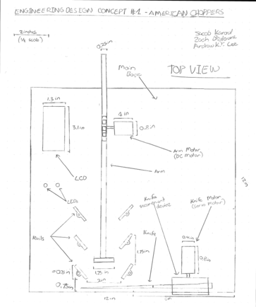
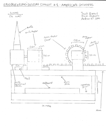
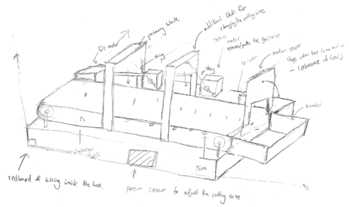
Other designs were also considered, one of which included a guillotine-style chopping element and a conveyer belt for moving the fruit. While this design addressed some stability shortcomings of the servo arm, it was ultimately dismissed due to a limited project budget of $25 and the complexities it may introduce (project time frame was just a few weeks).
Overall the fruit cutter performs alright on bananas and cucumbers but fails more often on round fruits such as apples and pears. See the below section for improvement ideas.
There are many, many changes I'd make if I were to do this project again but here are the main ones:

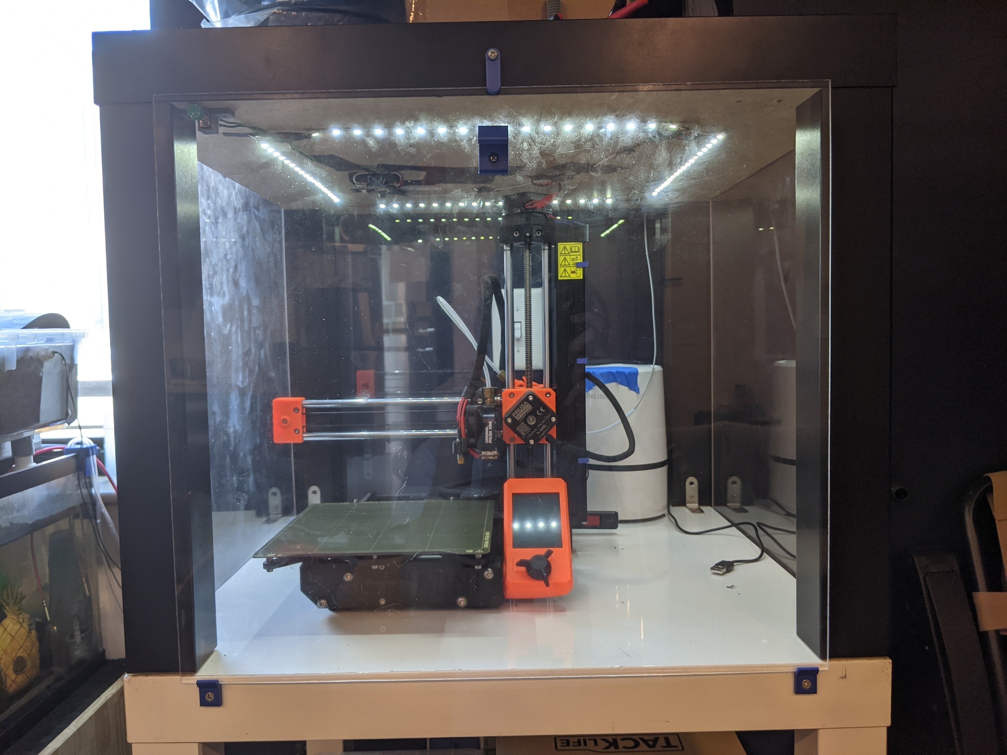
I got a 3D printer as a graduation gift in mid-2020 and, after relocating for a new job, decided to design and construct an enclosure for it.
I settled on using IKEA LACK tables, as they are very cheap ($5 apiece) and don't have built-in metal components so drilling into them isn't an issue.
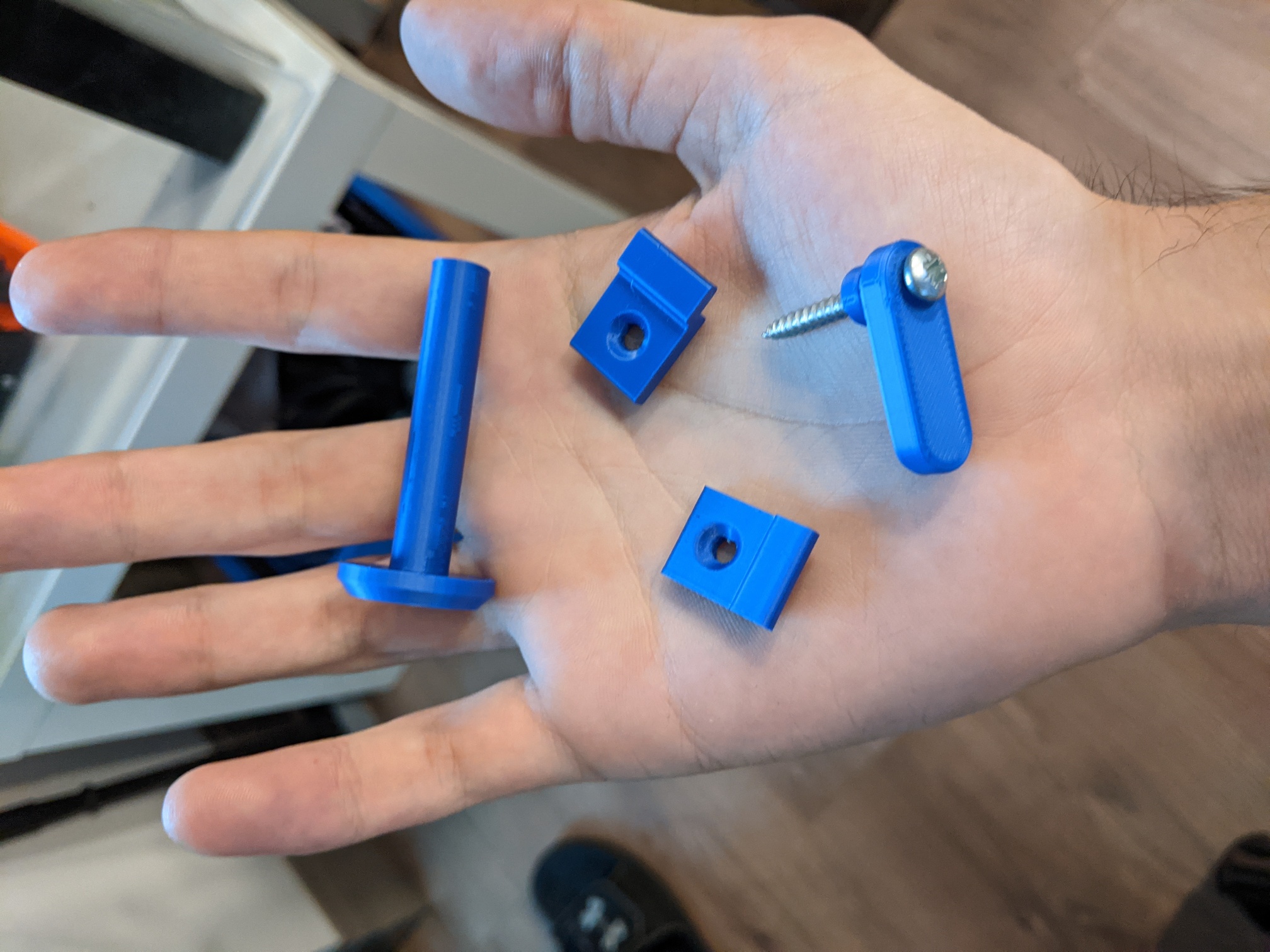
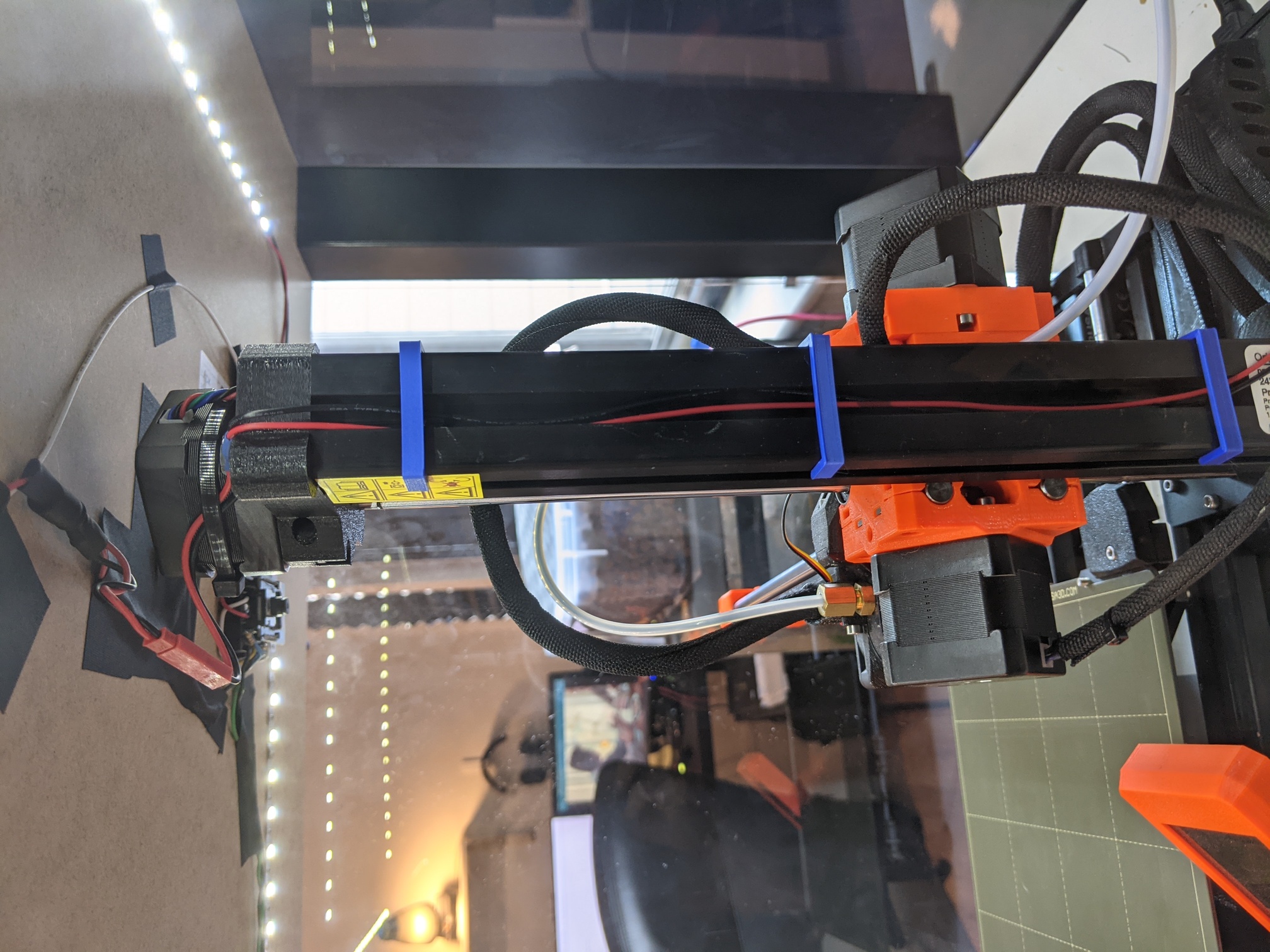
Four acrylic panes are used for the walls of the enclosure. Components were designed and 3D-printed to secure the panes to the LACK table.
An LED strip was also added to the underside of the enclosure. The LED strip chosen operated at 24V, the same voltage as the 3D-printer itself to avoid using a second power supply. This involved identifying the power pins within the 3D-printer and carefully bridging them.
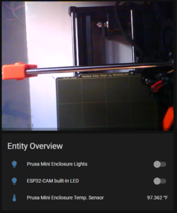
Later an ESP32-CAM board running ESPHome and DS18B20 temperature sensor were added and integrated into a Home Assistant instance.

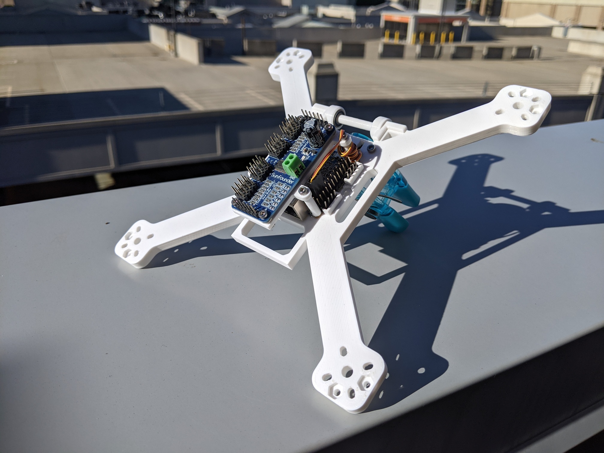
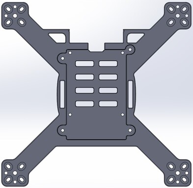
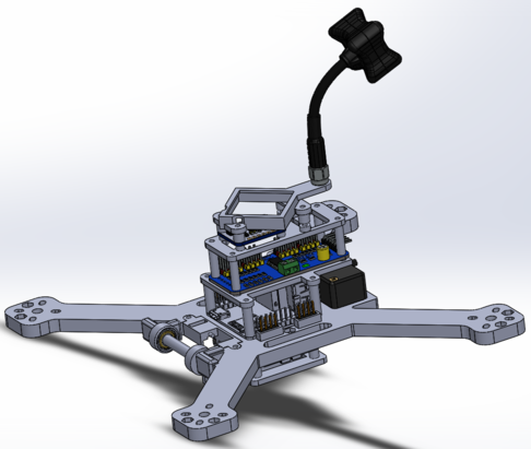
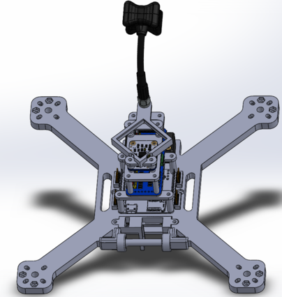
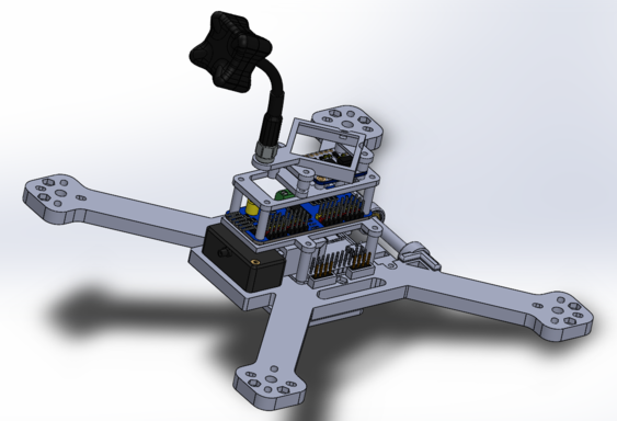
I designed a series of quadcopters after getting my first 3D printer. The only design goal for the physical construction was to max out the build plate dimensions of 180mm x 180mm.
The first iteration utilized a Raspberry Pi 3B as the onboard computer. It was quickly determined this would create too much drag and alternatives were then explored.
The SBC chosen for the next iteration was a NanoPi NEO2 due to its much smaller footprint (40mm x 40mm) and because it had a CVBS pin for integration with typical FPV equipment.
This system is designed to be used for aerial photography with the goal of complete autonomy. A removable camera gimbal with ball-bearings allows for tilt control and space is allotted on the other side for a micro LIDAR module for obstacle avoidance. The gimbal is driven by a micro servo, also discrete and removable.
Furthermore the quad has a cascading set of module boards on top with the option of adding more. These boards include an inertial-measurement unit (IMU), GPS module w/ discrete antenna and an FPV antenna.
This project was put on the backburner when my capstone project began and at the time of writing has not yet been revisited.

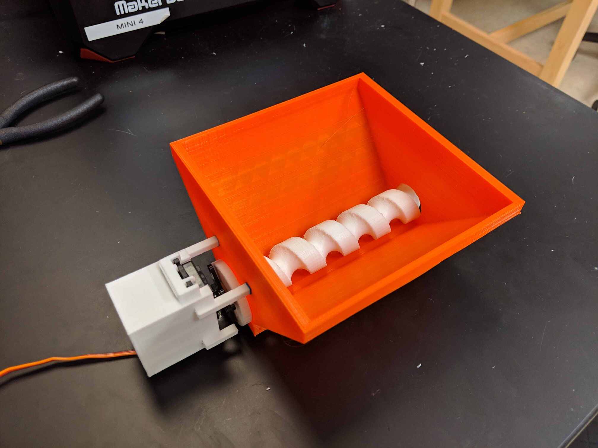
For a class project in embedded systems, a fellow computer engineer and I designed an automatic fish feeder for the PIC24 microcontroller. We chose a hopper-screw design due to its proven effectiveness and simplicity.
The feeder is programmed to release a set amount of food every 16 hours. As a single PIC24 8-bit timer only can only count to approximately 1 minute, two the PIC24's 8-bit timers were converted into a 16-bit timer. The screw is turned via a continuous rotation servo.
Eventually the PIC24 was replaced with a Raspberry Pi 3B to allow for easier integration with web servers for remote control. See the Modular Aquaponics project for more detail.
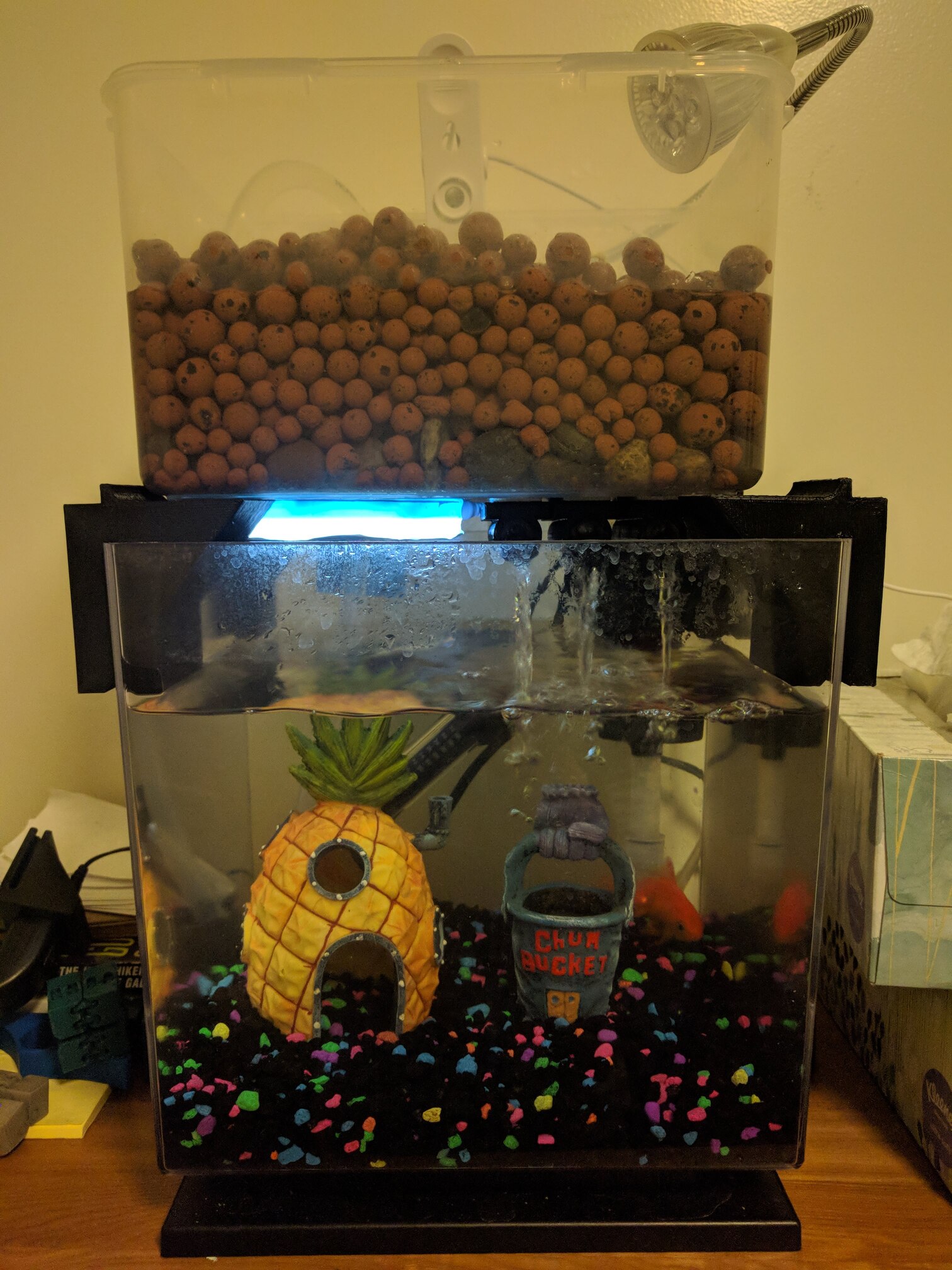
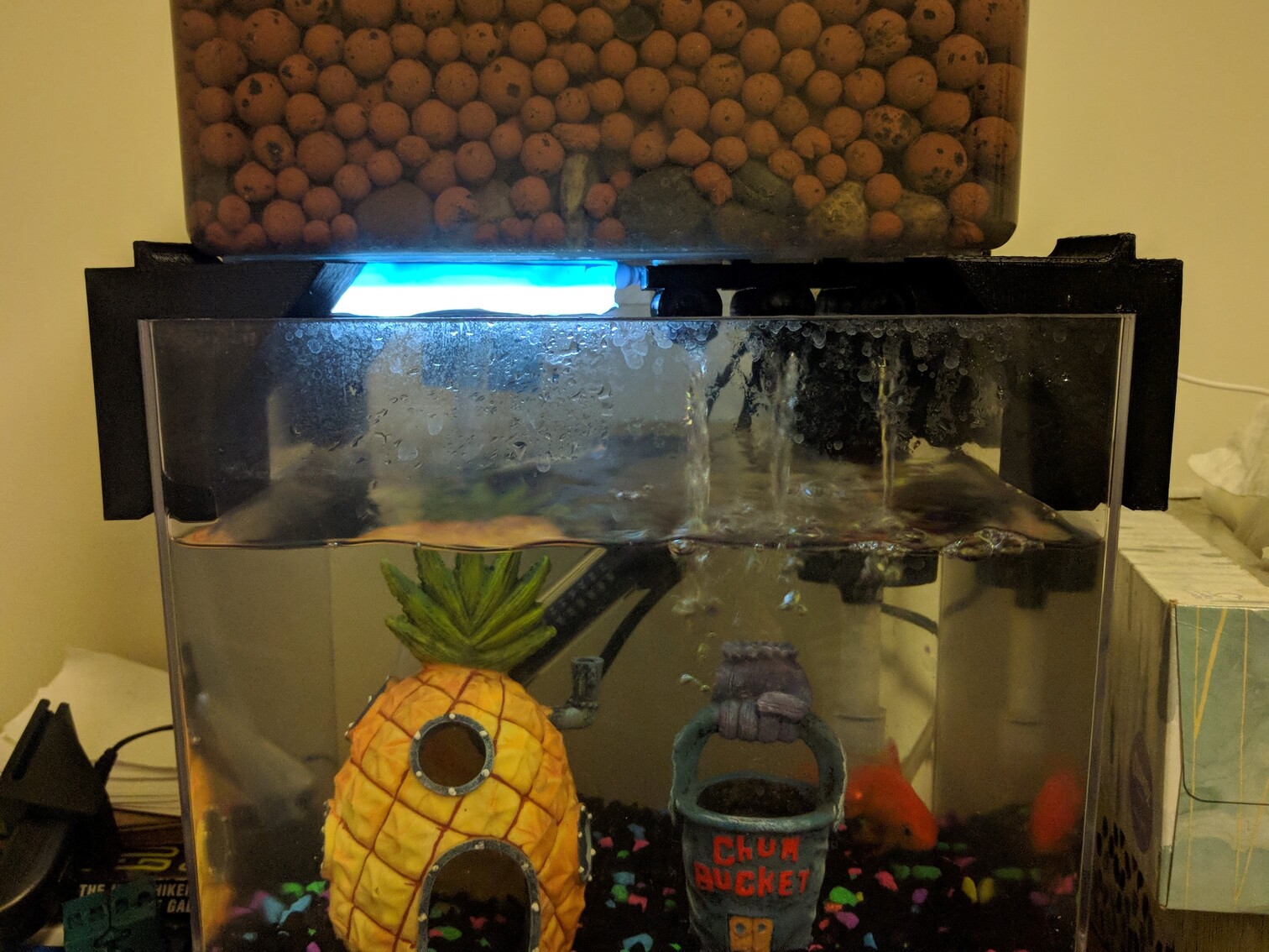
Back in my sophomore year of college I discovered aquaponics and decided to implement a system with my goldfish, Spartacus.
The goal of the project was to get practice in implementing aquaponics systems and to learn more about the topic in general. Given the very limited space in my dorm room, I chose an ebb-flow system design.
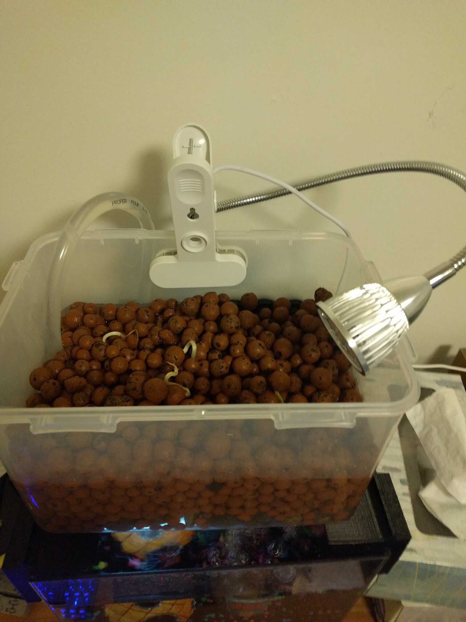
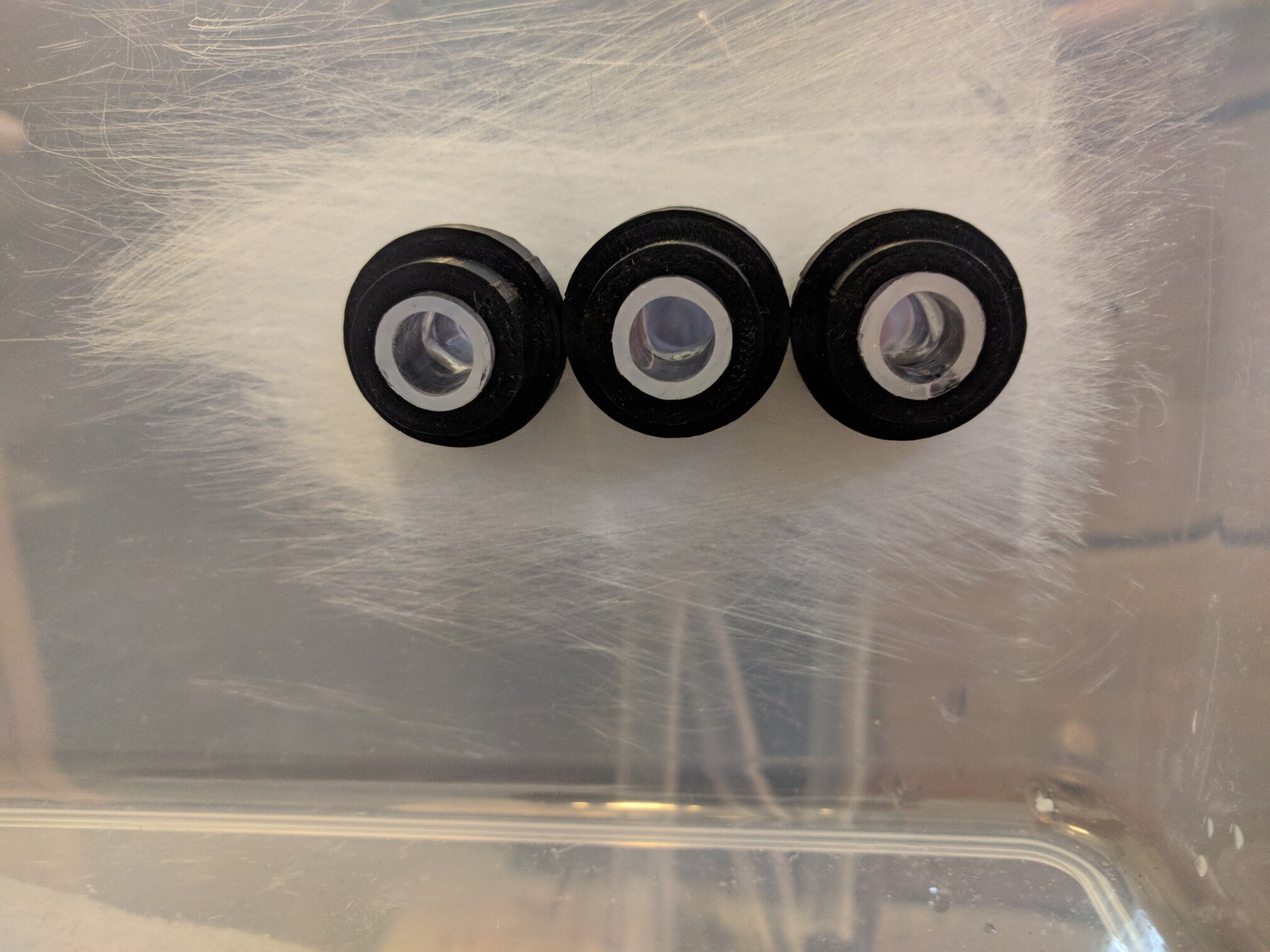
I designed and 3D-printed several components to support the grow bed above and route water from the grow bed down to the fish tank. A submersible water pump pumped water up. A clip-on grow light was added as well.
Over the course of the year I grew green onions and bean sprouts in this system. Though a fairly rudimentary setup I learned a lot about aquaponics and used that knowledge in the implementation of many more AP systems to come (see Modular Aquaponics and Apartment Aquaponics projects).
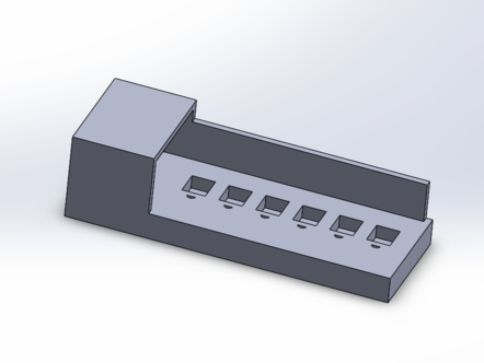
During my freshman year, after discovering Union College's Maker Studio, I decided to learn basic CAD and get a model printed. I decided a surge protector with remote control over each outlet would be useful.
A Particle Photon was chosen to control the surge protector.
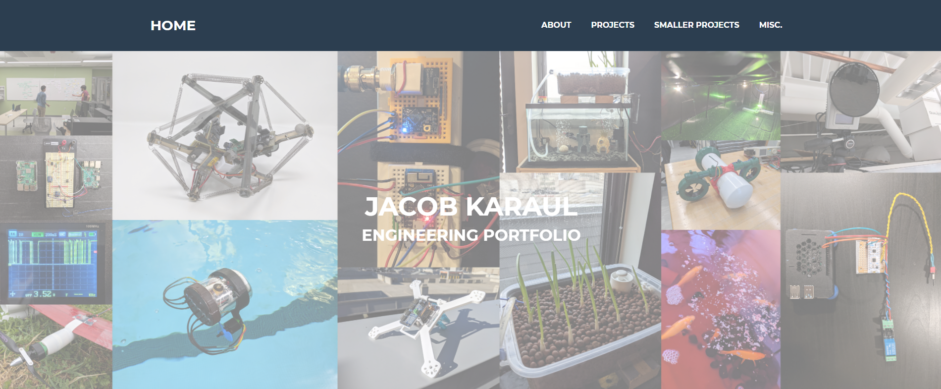
I have been maintaining an online portfolio to showcase my projects since my freshman year of college. This website is built using custom Bootstrap templates and CSS styling.